Model8555A
0
0
•
INPUT POWER AND
INTENSITY MODULATION
Set
115/230
switch
to
correspond with available
input
voltage. (The
instrument
is
fused for 115-
volt, 50(60 Hz operation; if 230-volt power is
used, refer
to
the display section service manual
for fuse replacement procedures.)
Set
!NT/EXT
switch
to
INT. (Set
to
EXT only if
CRT is
to
be
externally modulated normally
used with 1400-series time-domain plug-ins.)
Connect 50-ohm termination AT4.
FOCUS AND ASTIGMATISM ADJUSTMENTS
Set:
POWER
ON
(up; observe
that
ON
lamp lights)
BASE LINE CLIPPER, fully ccw
SCAN WIDTH (inner/red)
to
ZERO
INPUT ATTENUATION
to
10
dB
BANDWIDTH
to
0.3 kHz
SCAN TIME
PER
DIVISION
to
10
SECONDS
SCAN MODE
to
INT.
SCAN
TRIGGER
to
AUTO
TUNING STABILIZER
to
ON
FINE TUNE Control centered
LOG/LINEAR
to
LOG
LOG
REF
LEVEL Vernier: max
CCW
INTENSITY clockwise until trace
is
medium
bright (approx. 1 o'clock position).
BAND
to
0-2.05
GHz
VIDEO
FILTER
to
OFF
Adjust FOCUS
and
ASTIGMATISM controls until
combined effect produces best resolution (maxi·
mum roundness without fuzz)
of
the dot.
TRACE ALIGNMENT
Set SCAN TIME PER DIVISION
to
10 MILLI-
SECONDS.
If
not
already aligned, adjust TRACE ALIGN until
trace
is
aligned with horizontal line
of
graticule.
HORIZONTAL POSITION AND GAIN
For convenience in making these adjustments,
move trace to upper half
of
graticule
by
adjusting
the VERTICAL POSITION control.
Rotate
HORIZONTAL GAIN until trace is
of
minimum length.
Rotate
HORIZONTAL
POSITION until trace is
centered
on
CEN'rER
FREQUENCY line
of
grati-
cule.
Alternately
adjust HORIZONTAL POSITION/
GAIN controls until trace begins at first line
of
graticule and ends
at
last.
•
•
Operation
Readjust VERTICAL POSITION until trace aligns
with
bottom
line
of
graticule.
VERTICAL POSITION AND GAIN
Connect CAL
OUTPUT
(30
MHz/ -30 dBm) signal
to
RF
INPUT; select
100
kHz BANDWIDTH, 10
MHz PER DIVISION SCAN WIDTH
and
set
LOG
REF
LEVEL
to
+10 dBm.
Tune
FREQUENCY
to
align
LO
feedthru signal on
-3
graticule line. The 30
MHz
calibration signal
should appear at the CENTER
FREQUENCY
grat-
icule line with a
harmonic
at
the
+3 graticule line
(60 MHz). The dial marker should indicate approx-
imately
30
MHz.
Reduce
SCAN WIDTH PER DIVISION
to
0.2
MHz. Center signal on display
with
FREQUENCY
control. Reduce SUAN WIDTH PER DIVISION
to
2 kHz (keep signal centered on display
with
FINE
TUNE). Set LOG
REF
LEVEL
to
-30 dBm.
FINE
TUNE to
center
signal
on
display.
Rotate
AMPL
CAL until trace
is
centered
on
top
line
of
graticule
at
the
CENTER FREQUENCY
position.
Rotate
LOG
REF
LEVEL counterclockwise and
note
that
the
signal decreases
one
division
(10
dB)
for each calibrated switch position.
If
trace moves
one division per step in lower
part
of
graticule
but
the
amplitude creeps upward
near
top
of
graticule,
adjust VERTICAL GAIN until each
step
is equal.
LINEAR AND
LOGARITHMIC ADJUSTMENT
Rotate
LOG
REF
LEVEL
control
until signal
trace appears
on
fourth
graticule line
from
bot-
tom.
Set LOG /LINEAR switch
to
LINEAR
and
rotate
LOG
REF
LEVEL
control
until
1 m V /D
IV
is
matched
with the lighted index lamp.
Reading from
bottom
of
graticule (LIN scale),
signal amplitude should
be
7.1
millivolts.
If
it
is
not,
adjust
AMPL CAL for a signal
amplitude
of
7.1 millivolts.
Set LOG /LINEAR switch
to
LOG.
Rotate
LOG
REF
LEVEL eontrol until -30 dBm graduation
matches
the
lighted index lamp. Signal trace
should align with
top
(LOG
REF)
line
of
the
grati-
cule.
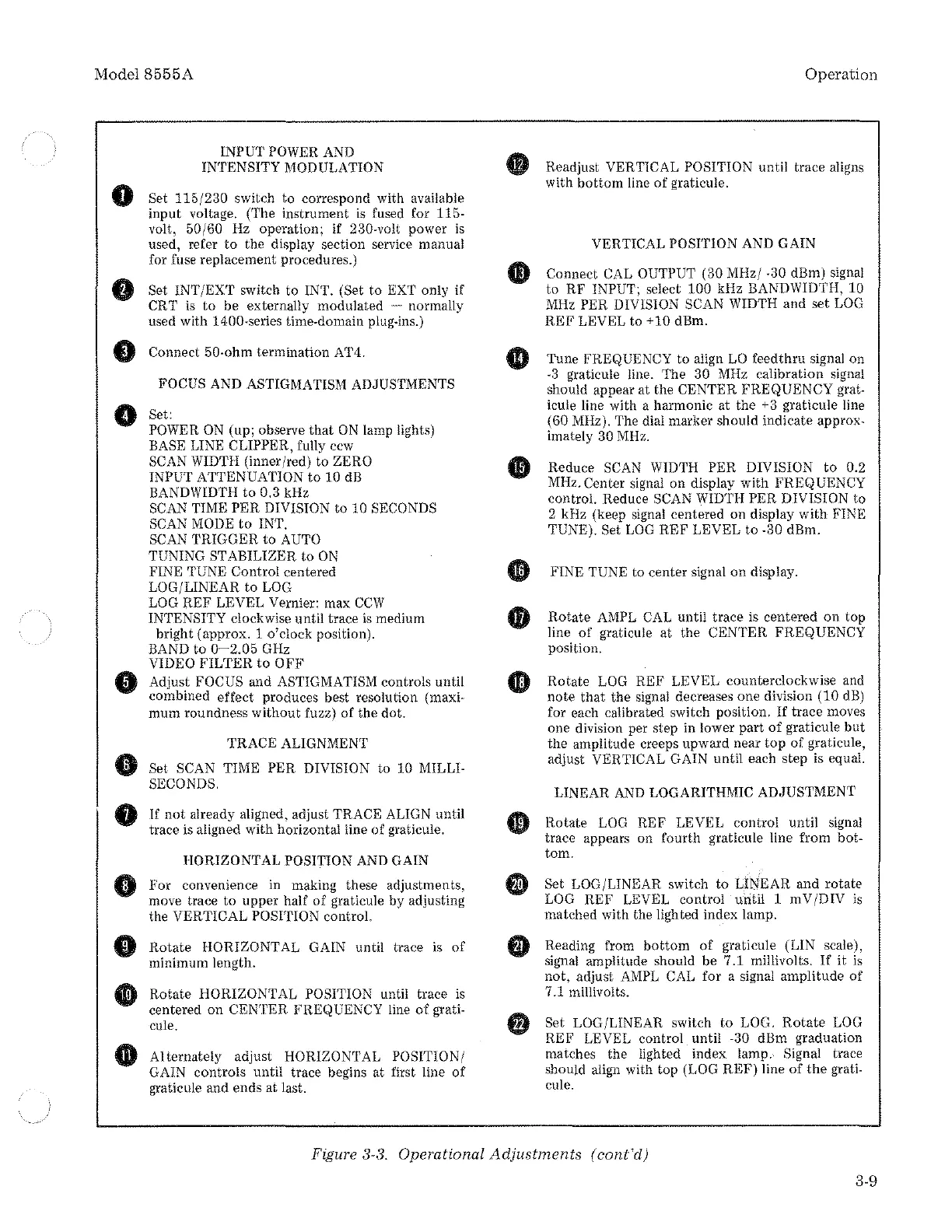
Figure 3-3. Operational
Adjustments
(
cont'd)
3-9