Installation
2-12.
The
offset
pin
of
the
three-prong
connec-
tor
is
the
grounding
pin.
When
operating
the
8756A from a two-contact
outlet,
the
protective
grounding
feature
may
be
preserved by using a
three-prong to two-prong
adapter
(USA connec-
tors only,
HP
Part
Number
1251-0048)
and
con-
necting
the
green
wire
of
the
adapter
to
ground.
2-13.
HP-IB Address Selection
2-14.
When
the 8756A is used
under
remote
control with
the
HP-
IB, the controller
on
the
bus
refers to
the
8756A by
an
HP-IB
"address".
The
8756A is preset
in
firmware to address
16,
and
is differentiated from
any
other
instrument
on
the
bus
by this address.
The
HP-IB
address
may
be
modified
by
a
front
panel
SHIFT
function.
2-15. Twenty-nine different address codes are
available (I to
29).
The
8756A is
shipped
from
the factory preset to address
16.
In
all
standard
8756A instruments,
the
HP-IB
address will be
read
by the processor from firmware
upon
ini-
tial power
on
only. This
HP-IB
address will
remain
in effect until the address is
changed
by
resetting
through
the
front
panel
[SHIFn
[LOCAL] function.
The
HP-IB
address
may
be
read directly from
the
front
panel
by pressing
[SHIFn
[LOCAL].
The
current
HP-IB address
is
then
displayed
on
the
CRT.
If
the
HP-IB
address
must
be
changed
from
that
which
is
dis-
played,
enter
the
new
address
and
press
[ENn
to
terminate
the entry.
The
display
should
now
show
the
new
HP-
IB address.
This
address is
not affected by
turning
the
LINE
switch off,
or
by a
PRESET
command.
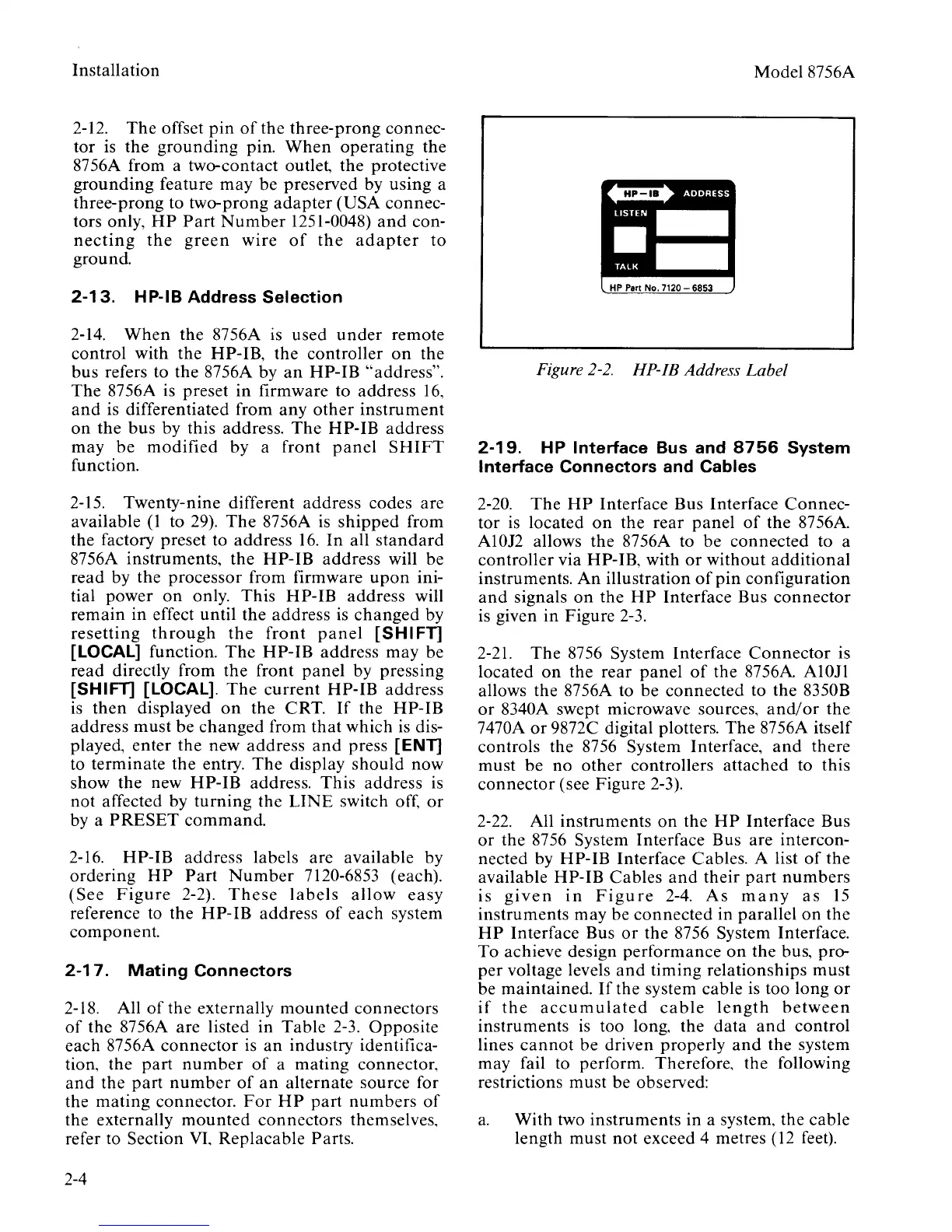
2-16. HP-IB address labels are available by
ordering
HP
Part
Number
7120-6853 (each).
(See
Figure
2-2).
These
labels
allow
easy
reference to the HP-IB address
of
each system
component.
2-17.
Mating
Connectors
2-18. All
of
the externally
mounted
connectors
of
the 8756A are listed in
Table
2-3.
Opposite
each
8756A
connector
is
an
industry identifica-
tion, the
part
number
of
a
mating
connector.
and
the
part
number
of
an
alternate source for
the
mating
connector.
For
HP
part
numbers
of
the externally
mounted
connectors themselves.
refer to Section
VI.
Replacable
Parts.
2-4
Model8756A
Figure
2-2.
HP-IB Address Label
2-19.
HP Interface Bus and
8756
System
Interface Connectors and Cables
2-20.
The
HP
Interface Bus Interface
Connec-
tor is located
on
the
rear
panel
of
the 8756A.
A10J2 allows the 8756A to
be
connected
to a
controller via
HP-IB, with
or
without
additional
instruments.
An
illustration
of
pin
configuration
and
signals
on
the
HP
Interface Bus
connector
is given
in
Figure
2-3.
2-21.
The
8756 System Interface
Connector
is
located
on
the rear
panel
of
the 8756A. A10Jl
allows the 8756A to
be
connected
to the 8350B
or
8340A swept microwave sources,
and/
or
the
7470A
or
9872C digital plotters.
The
8756A itself
controls the 8756 System Interface,
and
there
must
be
no
other
controllers
attached
to this
connector
(see Figure 2-3).
2-22. All
instruments
on
the
HP
Interface Bus
or
the 8756 System Interface Bus are intercon-
nected by
HP-
IB Interface Cables. A list
of
the
available HP-IB Cables
and
their
part
numbers
is
given
in
Figure
2-4.
As
many
as
15
instruments may be
connected
in
parallel
on
the
HP
Interface Bus
or
the 8756 System Interface.
To achieve design
performance
on
the bus, pro-
per
voltage levels
and
timing relationships
must
be maintained.
If
the system cable is too long
or
if
the
accumulated
cable
length
between
instruments
is
too long, the
data
and
control
lines
cannot
be driven properly
and
the system
may fail to perform. Therefore. the following
restrictions
must
be observed:
a.
With two instruments in a system, the cable
length must
not
exceed 4 metres (12 feet).

 Loading...


