Model 8901B
Service
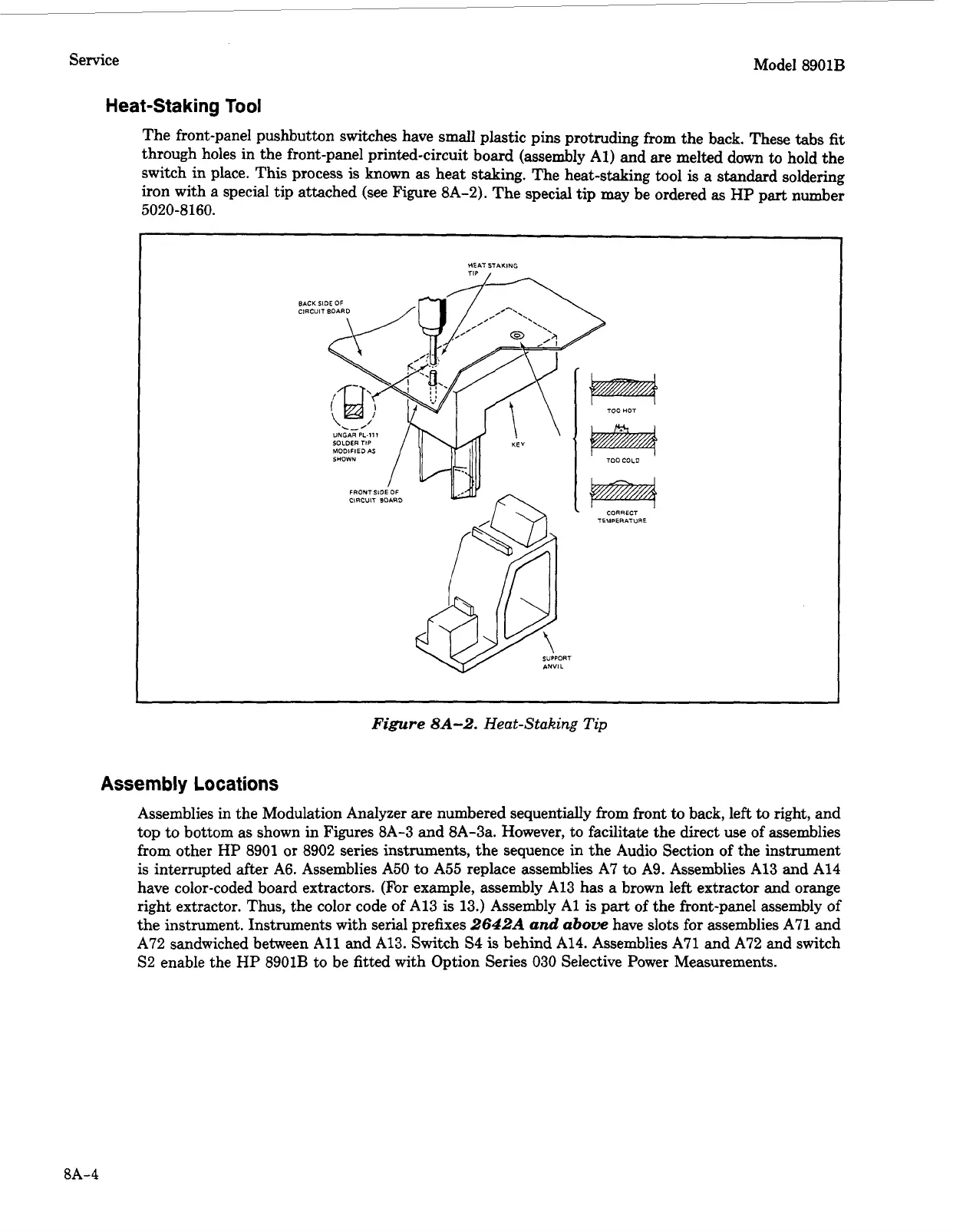
Heat-Staking
Tool
The front-panel pushbutton switches have small plastic pins protruding from the back. These tabs
fit
through holes in the front-panel printed-circuit board (assembly
Al)
and are melted down
to
hold the
switch in place. This process
is
known
as heat staking. The heat-staking tool
is
a standard soldering
iron with a special tip attached (see Figure 8A-2). The special tip may be ordered
as
HP
part
number
5020-8160.
CORRECT
TEMPERATURE
I
Figure
8A-2.
Heat-Staking
Tip
Assembly
Locations
Assemblies in the Modulation Analyzer are numbered sequentially from front
to
back, left
to
right, and
top to bottom as shown in Figures 8A-3 and 8A-3a. However, to facilitate the direct use of assemblies
from
other
HP
8901 or 8902 series instruments, the sequence in the Audio Section of the instrument
is
interrupted after A6. Assemblies A50 to A55 replace assemblies A7
to
A9. Assemblies A13 and A14
have color-coded board extractors. (For example, assembly A13 has a brown left extractor and orange
right extractor. Thus, the color code of A13 is 13.) Assembly
A1
is
part
of
the front-panel assembly of
the instrument. Instruments with serial prefixes
2642A
and
above
have slots for assemblies A71 and
A72 sandwiched between
All
and A13. Switch
S4
is
behind
A14.
Assemblies A71 and A72 and switch
S2
enable the
HP
8901B to be fitted with Option Series 030 Selective Power Measurements.
8A-4