Service Model
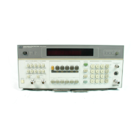
8901B
NOTE
The sufix
N
can also be two digits,
XY.
The displayed result
is
equivalent to
the display of
49.X
SPCL minus the display of
49.
Y
SPCL. For example,
49.3
SPCL
or
49.30
SPCL gives a display of the level from the RF Peak Detector
with respect to ground.
49.31
SPCL gives a display of the level from the RF
Peak Detector with respect to
the
level from
the
RF Peak Detector ground.
The rear-panel RECORDER output
is
connected
to
the
output
of
the
Voltmeter’s selector switch (see Service Sheet
15).
During normal operation,
the selector
is
constantly being switched between the
various
inputs. Each
voltage measurement also includes a separate measurement of ground. The
displayed result
is
derived from the difference between the selected voltage
and ground readings.
The switching at the RECORDER output can be halted
by
keying
in
Special
finction
49.XY
with
X
equal to
0
or
8
and
Y
equal to the desired input.
The
dc level at the RECORDER output
is
constant and equal to the selected
input; the displayed measurement result
is
equal to the result using Special
finction
49.
Y.
This
feature
is
useful for troubleshooting the Voltmeter and
for improving the accuracy of
the
RF Power measurement (see
Recorder
Output
in
Section
3).
50.N Display Internal Voltages.
The Voltmeter measures and displays the internal voltage
(in
volts)
selected by
N.
See also the previous note.
Ground. See Service Sheet
15.
-15V
Supply. The display should read between
2.8500
and
3.1500.
See
Service Sheet
15.
-5V
Supply. The display should read between
2.8500
and
3.1500.
See Service Sheet
15.
+5V
Supply. The display should read between
2.8500
and
3.1500.
See Service Sheet
15.
+15V
Supply. The display should read between
2.8500
and
3.1500.
See Service Sheet
15.
+40V
Supply. The display should read between
2.8500
and
3.1500.
See Service Sheets
15
and
20.
IF
Amplifier/Detector (option series
030.)
See Service Sheet
34.
N=O
N=l
N=2
N=3
N=4
N=5
N=6
52.N Read-only Memory Verification.
The Controller displays the checksum of the read-only memory
(ROM)
specified by
N.
When specifying a
ROM,
use
N=l
through
3.
The display
is
in the form <actual
checksum>.<expected checksum>. An initial zero
(or
zeros) will be blanked. Thus, for example,
24.024
would be a valid checksum,
24.124
would be invalid. The display times out after approximately
5s.
See
Service Sheet
24.
54.N Local Oscillator Test.
The Controller sequences the local oscillator
(LO)
through groups of tests
specified by
N
and returns a fault code corresponding to the tests that failed.
For
N=l
to
N=5,
four
tests are performed for each group.
If
all tests in the group pass,
0
will be displayed.
If
any tests fail,
the test numbers appear on the display
in
the positions indicated. (The digit positions are numbered
under the display window.) All leading zeros in the display are blanked. For example,
in
the group
defined by
N=1,
a
simultaneous time base (Test
2)
and
HF
VCO
or
Divider (Test
4)
failure will result
in the display
“
20004”
(three leading zeros blanked). The
tests
are continuously sequenced, and the
display will be updated
as
the fault
is
corrected. The tests are most easily visualized by referring
to
Figures
8D-1
through
8D-4.
Performs all tests in the group listed for
N=l
through
N=5
(below). Displays the number
of
the
first
test that failed.
If
no test fails,
0
is displayed.
N=O
8B-8
Special Functions

 Loading...