Model 8901B Service
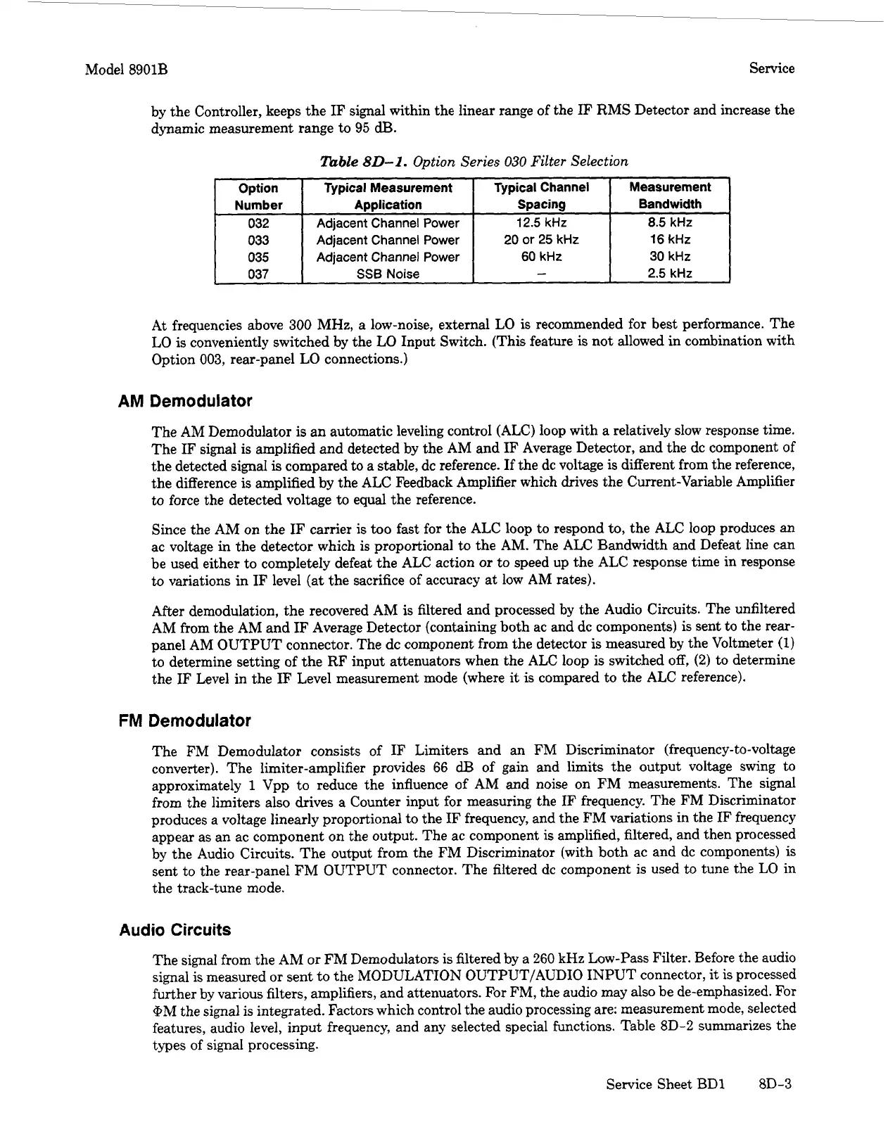
Option Typical Measurement Typical Channel
Number
Application Spacing
032
Adjacent Channel Power 12.5 kHz
033 Adjacent Channel Power
20
or
25
kHz
035
Adjacent Channel Power 60 kHz
037
SSB
Noise
-
by the Controller, keeps the
IF
signal within the linear range of the
IF
RMS Detector and increase the
dynamic measurement range to 95
dB.
Measurement
Bandwidth
8.5
kHz
16 kHz
30
kHz
2.5
kHz
At
frequencies above
300
MHz,
a low-noise, external LO is recommended for best performance. The
LO is conveniently switched by the
LO
Input Switch. (This feature
is
not allowed in combination with
Option
003,
rear-panel
LO
connections.)
AM
Demodulator
The
AM
Demodulator
is
an automatic leveling control (ALC) loop with a relatively slow response time.
The
IF
signal
is
amplified and detected by the AM and
IF
Average Detector, and the dc component
of
the detected signal
is
compared to a stable, dc reference.
If
the dc voltage is different from the reference,
the difference is amplified by the ALC Feedback Amplifier which drives the Current-Variable Amplifier
to force the detected voltage to equal the reference.
Since the AM on the
IF
carrier is too fast for the ALC loop to respond to, the ALC loop produces an
ac voltage in the detector which is proportional
to
the AM. The ALC Bandwidth and Defeat line can
be used either to completely defeat the ALC action
or
to speed up the ALC response time in response
to
variations in
IF
level
(at
the sacrifice
of
accuracy at low AM rates).
After demodulation, the recovered AM is filtered and processed by the Audio Circuits. The unfiltered
AM from the AM and
IF
Average Detector (containing both ac and dc components) is sent to the rear-
panel AM OUTPUT connector. The dc component from the detector
is
measured by the Voltmeter
(1)
to determine setting of the RF input attenuators when the ALC loop
is
switched off,
(2)
to determine
the
IF
Level in the
IF
Level measurement mode (where
it
is compared to the ALC reference).
FM
Demodulator
The FM Demodulator consists of
IF
Limiters and an FM Discriminator (frequency-to-voltage
converter). The limiter-amplifier provides
66
dB
of gain and limits the output voltage swing to
approximately
1
Vpp to reduce the influence of AM and noise on FM measurements. The signal
from the limiters also drives a Counter input for measuring the
IF
frequency. The FM Discriminator
produces a voltage linearly proportional to the
IF
frequency, and the FM variations in the
IF
frequency
appear as an ac component on the output. The ac component is amplified, filtered, and then processed
by the Audio Circuits. The output from the FM Discriminator (with both ac and dc components)
is
sent to the rear-panel FM OUTPUT connector. The filtered dc component is used to tune the LO in
the track-tune mode.
Audio Circuits
The signal from the AM or FM Demodulators is filtered by a
260
kHz
Low-Pass Filter. Before the audio
signal is measured
or
sent to the MODULATION OUTPUT/AUDIO INPUT connector,
it
is
processed
further by various filters, amplifiers, and attenuators.
For
FM, the audio may also be de-emphasized. For
@M the signal
is
integrated. Factors which control the audio processing are; measurement mode, selected
features, audio level, input frequency, and any selected special functions. Table
8D-2
summarizes the
types
of
signal processing.
Service Sheet BD1
8D-3
 Loading...


