Service
Power Meter Range
1
(most sensitive)
2
3
4
5
(least sensitive)
Model 8901B
Attenuator
1
(dB)
Attenuator
2
(dB)
0
0
0
20
0
40
40
20
40
40
State
of
Frequency
Offset
Mode
Not
Off
set
Offset
Offset
Offset
The amplified ac signal, which
is
proportional to the input power,
is
converted to dc by the Synchronous
Detector. The Synchronous Detector is a unity-gain amplifier which alternates between a non-inverting
configuration and an inverting configuration
at
a
220 Hz rate. The 220 Hz drive signal is synchronized
with the signal that drives the Chopper in the Power Sensor. Since the phase shift between the signal
from the Power Sensor Chopper and the input of the Synchronous Detector is zero, the ac signal is
full-wave rectified and has a dc component proportional to the output of the RF Power Sensing Element
of
the Power Sensor. After filtering by the Noise Filters, the dc voltage representing the recovered power
level of the input signal
is
measured by the Voltmeter. The 220
Hz
drive signal for the Power Sensor
Chopper and for the Synchronous Detector
is
generated by the 220 Hz Multivibrator.
The Ground Regulator
is
a unity-gain, non-inverting amplifier which assures minimum voltage
difference between the Sensor Ground and the Power Meter Assembly ground. High current flow
through the ground return of the interconnecting cable causes the voltage difference, especially
if
the
cable
is
quite long.
The Zeroing Control Digital-to-Analog Converter (DAC) compensates for the small dc offset voltage
generated by the Power Sensing Element when no RF
is
present. To zero the sensor, the Controller
switches the Input Switch of the Sensor Module away from the Power Sensor and measures the output
from the Power Meter.
If
the output does not correspond to
OW
power, the Zeroing Control DAC
is
programed to inject a current into the
RF
Power Sensing Element to cancel the offset. (To keep
the Synchronous Detector in its most-linear range, the voltage corresponding to
OW
input power is
offset slightly above
0
Vdc. The offset voltage
is
subtracted out by the Controller when actual power
measurements are made.) The DAC remains set until re-zeroing
is
requested.
The Sensor Module Switch Control and Switch Drive One-Shot control switching of the Input Switch
in the external Sensor Module. The circuitry
is
designed to drive latching-type
RF
switches which may
or
may not have automatic drive disconnect. The Power Reference Oscillator Control switches on the
50
MHz Oscillator when requested. To enable the assembly of a user-built sensor module, the switching
voltages are made available at the rear-panel
REMOTE
CONTROL RF SWITCH connectors.
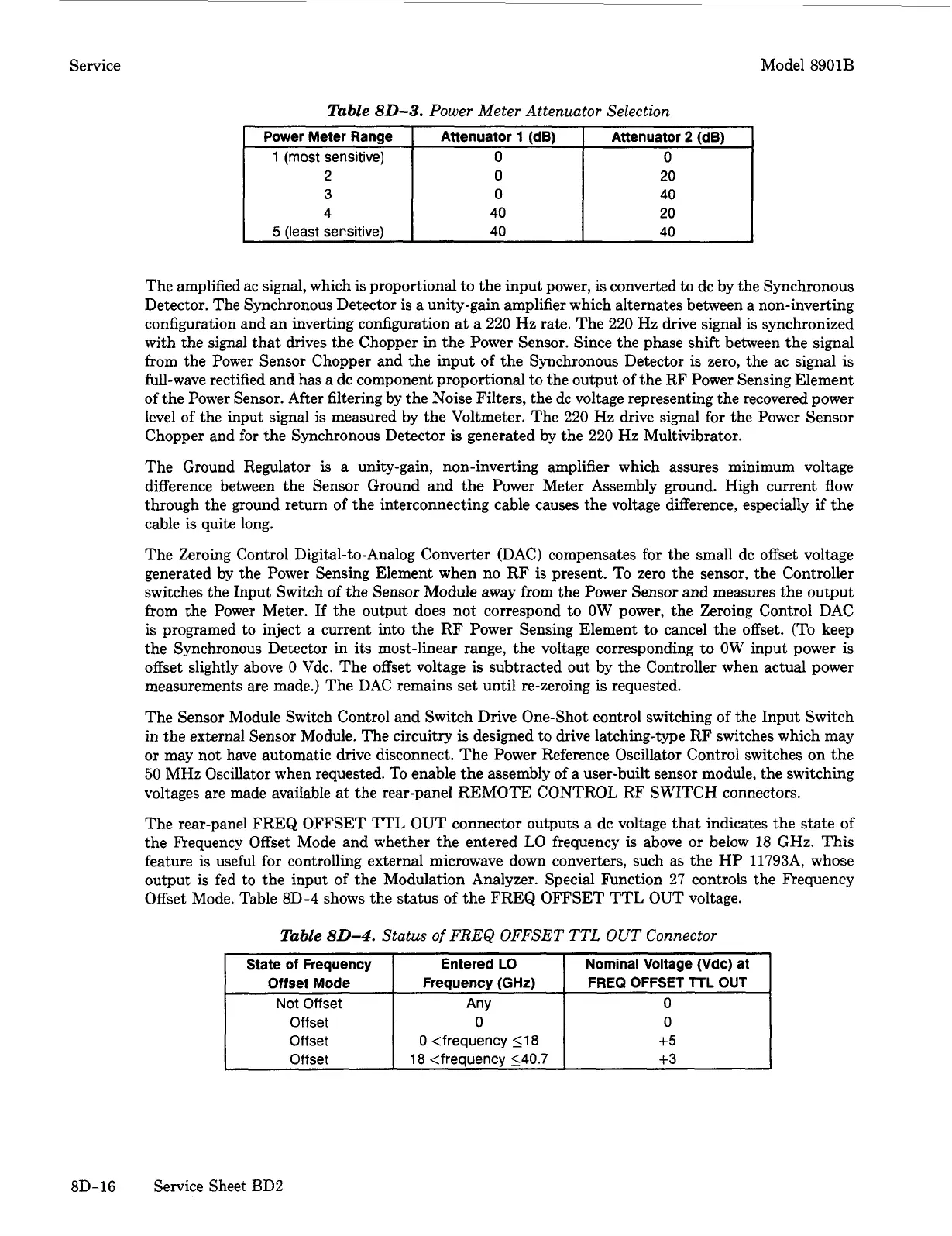
The rear-panel FREQ
OFFSET
TTL
OUT
connector outputs a dc voltage that indicates the state of
the Frequency Offset Mode and whether the entered
LO
frequency is above
or
below 18
GHz.
This
feature is useful for controlling external microwave down converters, such as the HP 11793A, whose
output
is
fed to the input of the Modulation Analyzer. Special Function 27 controls the Frequency
Offset Mode. Table 8D-4 shows the status of the FREQ OFFSET TTL OUT voltage.
Entered
LO
Frequency
(GHz)
Nominal Voltage (Vdc)
at
FREQ OFFSET
lTL
OUT
Any
0
0
<frequency
118
+5
18
<frequency
540.7
+3
0
0
Table
80-4.
Status
of
FREQ
OFFSET
TTL
OUT
Connector
8D-16
Service Sheet
BD2
 Loading...


