Model 8901B
Service
FM
DE-EMPHASIS
(PSI
25
50
75
750*
5.
Set the synthesizer frequency
to
300 Hz. Set HP FILTER to 300 Hz. The waveform should have
an ac amplitude of 1.3 to
1.7
Vpp. If faulty, see Service Sheet 13 and check the 300 Hz High-Pass
Filter.
Waveform Amplitude Limits (Vpp)
Minimum Maximum
1.3
1.7
1.3
1.7
1.3
1.7
1.3
1.7
6.
Set
the synthesizer frequency
to
50
Hz. Set
HP
FILTER
to
50
Hz. The waveform should have
an ac amplitude of 1.3 to
1.7
Vpp. If faulty, see Service Sheet 13 and check the
50
Hz High-Pass
Filter.
7.
Set the synthesizer frequency to 3 kHz. Set HP FILTER
off
and the LP FILTER to 3 kHz. The
waveform should have an ac amplitude of
1.2
to 1.8 Vpp.
If
faulty, see Service Sheet 13 and check
the 3 kHz Low-Pass Filter.
8.
Set the LP FILTER
off
and FM DE-EMPHASIS
to
PRE-DISPLAY. Set the synthesizer
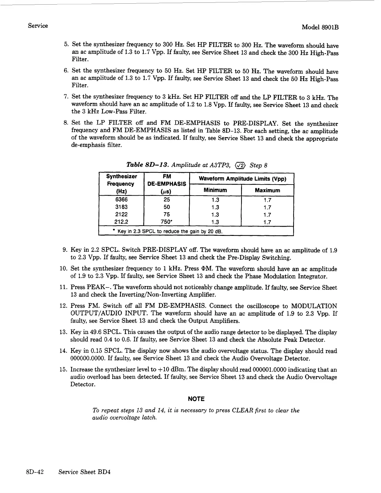
frequency and FM DE-EMPHASIS as listed in Table
8D-13.
For each setting, the ac amplitude
of the waveform should be as indicated.
If
faulty, see Service Sheet 13 and check the appropriate
de-emphasis filter.
lbble
80-13.
Amplitude at
A3TP3,
@
Step
8
Synthesizer
Frequency
6366
31
83
21
22
21
2.2
(Hz)
~ ~~
Kev
in
2.3
9. Key in
2.2
SPCL. Switch PRE-DISPLAY
off.
The waveform should have an ac amplitude of 1.9
to 2.3 Vpp. If faulty, see Service Sheet 13 and check the Pre-Display Switching.
10.
Set the synthesizer frequency to
1
kHz. Press
@M.
The waveform should have an ac amplitude
of 1.9 to 2.3 Vpp.
If
faulty, see Service Sheet 13 and check the Phase Modulation Integrator.
11.
Press PEAK-. The waveform should not noticeably change amplitude. If faulty, see Service Sheet
13 and check the Inverting/Non-Inverting Amplifier.
12. Press FM. Switch
off
all FM DE-EMPHASIS. Connect the oscilloscope to MODULATION
OUTPUT/AUDIO INPUT. The waveform should have
an
ac amplitude of 1.9 to 2.3 Vpp. If
faulty, see Service Sheet 13 and check the Output Amplifiers.
13. Key in 49.6 SPCL. This causes the output of the audio range detector to be displayed. The display
should read
0.4
to 0.6.
If
faulty, see Service Sheet 13 and check the Absolute Peak Detector.
14.
Key in
0.15
SPCL. The display now shows the audio overvoltage status. The display should read
000000.0000.
If
faulty, see Service Sheet 13 and check the Audio Overvoltage Detector.
15.
Increase the synthesizer level to
+10
dE3m. The display should read
000001.0000
indicating that an
audio overload has been detected.
If
faulty, see Service Sheet 13 and check the Audio Overvoltage
Detector.
NOTE
To
repeat steps
13
and
14,
it
is
necessary
to
press
CLEAR
first to clear the
audio overvoltage latch.
8D-42 Service Sheet BD4


 To Next Page
 Loading...