Model 8901B Service
(J3)
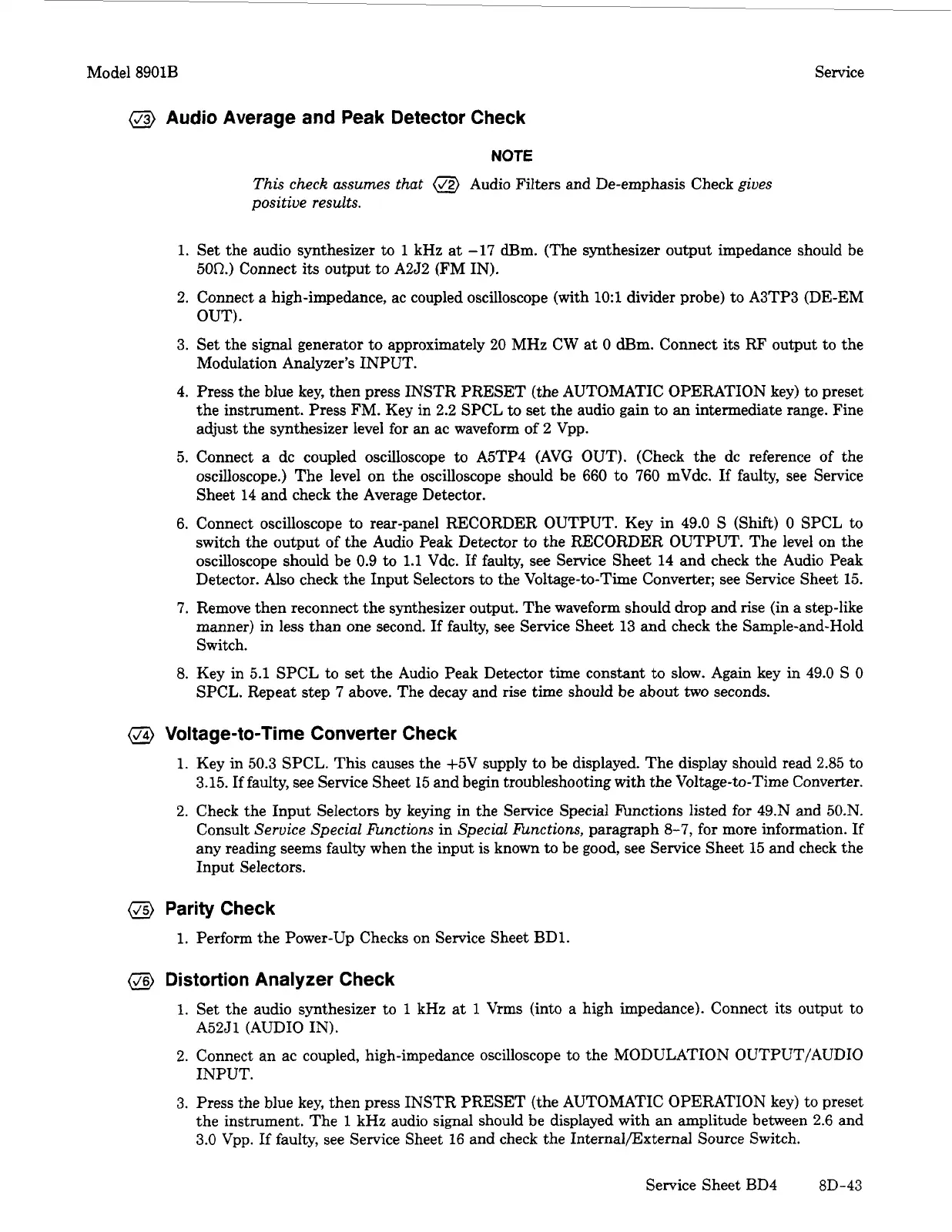
Audio Average and Peak Detector Check
NOTE
This check assumes that
@
Audio Filters and De-emphasis Check gives
positive results.
1.
Set the audio synthesizer
to
1
kHz at
-17
am. (The synthesizer output impedance should be
500.) Connect its output to A2J2 (FM IN).
2. Connect a high-impedance, ac coupled oscilloscope (with
1O:l
divider probe) to A3TP3 (DE-EM
OUT).
3.
Set the signal generator to approximately 20 MHz CW at
0
dBm. Connect its RF output to the
Modulation Analyzer’s INPUT.
4. Press the blue key, then press INSTR PRESET (the AUTOMATIC OPERATION key) to preset
the instrument. Press FM. Key in 2.2 SPCL
to
set the audio gain
to
an
intermediate range. Fine
adjust the synthesizer level for an ac waveform
of
2 Vpp.
5. Connect a dc coupled oscilloscope to A5TP4 (AVG OUT). (Check the dc reference of the
oscilloscope.) The level on the oscilloscope should be
660
to
760
mVdc.
If
faulty, see Service
Sheet 14 and check the Average Detector.
6.
Connect oscilloscope to rear-panel RECORDER OUTPUT. Key in 49.0
S
(Shift)
0
SPCL
to
switch the output of the Audio Peak Detector
to
the RECORDER OUTPUT. The level on the
oscilloscope should be 0.9
to
1.1
Vdc.
If
faulty, see Service Sheet 14 and check the Audio Peak
Detector. Also check the Input Selectors to the Voltage-to-Time Converter; see Service Sheet
15.
7.
Remove then reconnect the synthesizer output. The waveform should drop and rise (in a step-like
manner) in less than one second.
If
faulty, see Service Sheet 13 and check the Sample-and-Hold
Switch.
8.
Key in 5.1 SPCL to set the Audio Peak Detector time constant to slow. Again key in 49.0
S
0
SPCL. Repeat step
7
above. The decay and rise time should be about
two
seconds.
@
Voltage-to-Time Converter Check
1.
Key in 50.3 SPCL. This causes the +5V supply
to
be displayed. The display should read 2.85 to
3.15.
If
faulty, see Service Sheet
15
and begin troubleshooting with the Voltage-to-Time Converter.
2.
Check the Input Selectors by keying in the Service Special Functions listed for 49.N and 50.N.
Consult Service Special finctions in Special finctions, paragraph
8-7,
for more information.
If
any reading seems faulty when the input
is
known
to
be good, see Service Sheet 15 and check the
Input Selectors.
(J5)
Parity Check
1.
Perform the Power-Up Checks on Service Sheet BD1.
(J6)
Distortion Analyzer Check
1.
Set the audio synthesizer to
1
kHz
at
1
Vrms (into a high impedance). Connect its output to
2.
Connect an ac coupled, high-impedance oscilloscope to the MODULATION OUTPUT/AUDIO
3.
Press
the blue key, then press INSTR PRESET (the AUTOMATIC OPERATION key) to preset
the instrument. The
1
kHz audio signal should be displayed with an amplitude between 2.6 and
3.0
Vpp. If fauIty, see Service Sheet
16
and check the Internalmxternal Source Switch.
A52J1 (AUDIO IN).
INPUT.
Service Sheet BD4
8D-43


 To Next Page
 Loading...