1-4 HP 8970B Option 020 Service Manual Supplement
Block Diagram and Parts List
Front End
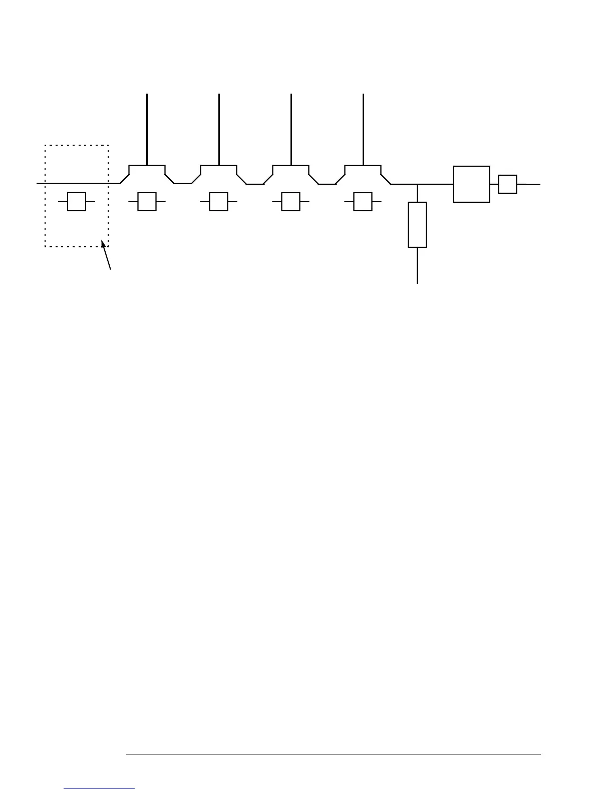
Figure 1-3: Schematic Representation of Input Assembly
This is a schematic representation of the RF input assembly. The amplifier section and
each and each of the attenuator sections are switchable by the control lines.
On units using the Input Assembly 08970-60125, the Limiter suppresses externally
generated transients.
In Figure 1-1 the numbers in brackets inside the input assembly refer to the wire colors.
The numbers at the side of the second convertor refer to the wire colors attached to the
connector which connects up to the second convertor.
10 dB
PAD
20 dB
AMP
10 dB
PAD
10 dB
PAD
Detector
3 GHz
LPF
2dB
PAD
PAD 1 20 dB
Amp
PAD 2 PAD 3
Limiter
Limiter (on 08970-60125
Input Assembly only).