5-2 HP 8970B Option 020 Service Manual Supplement
Fault-Finding Tips
General
General
The Option 20 front end is relatively easy to fault find because it is a combination of
defined RF components.
Instead of using the noise source it is possible to use a signal generator to inject a signal
and then trace the signal levels through the RF paths to the 300 MHz second IF using a
spectrum analyzer. It is much easier to do it this way because the signals can be seen on
the spectrum analyzer display.
Filter (0955-0634)
The specifications on this part are:
The best way to measure this part is to use a network analyzer. An alternate way is to use
a spectrum analyzer, e.g. 8593E with a tracking generator or a separate sweeper.
Verify over the frequency ranges above that the insertion losses are correct.
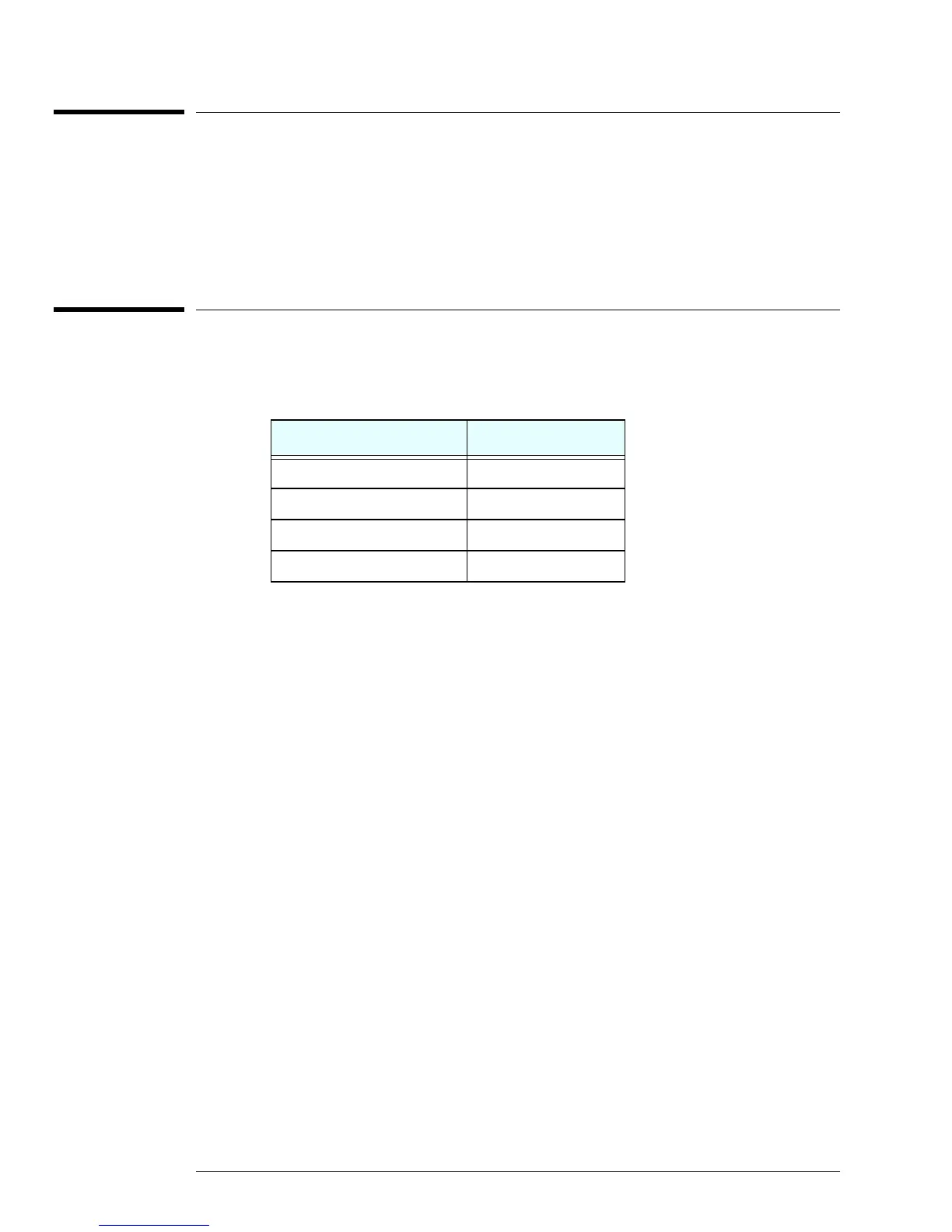
Table 5-1: 2050 MHz Low Pass Filter Specifications
Frequency Insertion Loss
10 MHz to 2050 MHz < 0.5 dB
2.35 GHz to 3.85GHz > 35 dB
3.85 GHz to 13.0 GHz > 65 dB
13.0 GHz to 26.5 GHz > 50 dB