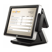
HP ap5000 All-In-One Point of Sale System 609153-001 page 2
Hewlett-Packard Vision Diagnostics (Windows Systems)
The Hewlett-Packard Vision Diagnostics utility allows you to view information about the hard-
ware configuration of the computer and perform hardware diagnostic tests on the subsystems of
the computer. The utility simplifies the process of effectively identifying, diagnosing, and iso-
lating hardware issues.
Use HP Vision Diagnostics to determine if all the devices installed on the computer are recog-
nized by the system and functioning properly. Running tests is optional but recommended after
installing or connecting a new device.
To access HP Vision Diagnostics, you must burn the utility onto a CD or copy it onto a USB
flash drive then boot to the CD or USB flash drive. It can also be downloaded from http://
www.hp.com and either burned to CD or installed to a USB flash drive.
1. In Windows Explorer, go to C:\SWSetup\ISOs and burn the file Vision Diagnostics.ISO to a
CD or copy it to a USB flash drive.
2. While the computer is on, insert the CD in the optical drive or USB flash drive in a USB port.
3. Shut down the operating system and turn off the computer.
4. Turn on the computer. The system will boot into HP Vision Diagnostics.
NOTE: If the system does not boot to the CD in the optical drive or to the USB flash drive,
you may need to change the boot order in the Computer Setup (F10) utility.
5. At the boot menu, select either the HP Vision Diagnostics utility to test the various hardware
components in the computer or the HP Memory Test utility to test memory only.
NOTE: The HP Memory Test is a comprehensive memory diagnostic utility that is run as a
stand-alone application, outside of HP Vision Diagnostics.
6. If running HP Vision Diagnostics, select the appropriate language and click Continue.
7. In the End User License Agreement page, select Agree if you agree with the terms. The HP
Vision Diagnostics utility launches with the Survey tab displayed.
Calibrating the Touch Screen
NOTE: You may want to connect a mouse (not included) to the system for this procedure.
After the operating system is installed, you will need to calibrate the touch screen.
1. Launch the TouchMon utility by right-clicking on the TouchMon icon in the system tray and
selecting 4 points calibration or selecting Start > All Programs > HP Touch > HP
TouchMon Calibration.
2. When you see a red circle in the corner of the screen, touch the center of the circle with your
finger and continue touching it until the progress counter changes to OK. A new red circle
will then appear in another corner of the screen.
3. Repeat Step 2 for each corner of the screen. When the process is complete, the utility will
close and return you to the Windows desktop.
Configuring the MSR and VFD Customer Display
To configure the MSR and VFD, refer to the HP Point of Sale Configuration Guide (available in
English only). The guide is available on the system's hard drive. In Windows XP or Windows
Embedded POSReady 2009, select Start > All Programs > HP Point of Sale Information to
access the guide. In Windows 7, select Start > HP Point of Sale Information to access the guide.
Configuring the COM Port for the VFD Customer Display
You can connect the VFD customer display to either the COM1 port or the COM2 port. The
COM port must be configured for 5 volts in the Computer Setup utility for the VFD customer
display to function properly. The VFD is connected to the COM2 port from the factory and the
COM2 port is already configured for 5 volts.
NOTE: Do not connect the VFD customer display to the COM3 port.
1. Press the power button to turn off the computer.
2. Press the power button again to turn on the computer and press the F10 key before the system
boots to the operating system to enter the Computer Setup utility.
3. Note which COM port (COM1 or COM2) on the rear panel is connected to the VFD customer
display.
4. In the Computer Setup utility, go to Advanced > Super IO Configuration > Serial Port1
Standard Mode/5V or Serial Port2 Standard Mode/5V and change the setting to 5 V.
NOTE: If you set the Serial Port2 Standard Mode/5V port to 5 V, you must set the Serial
Port1 Standard Mode/5V to Standard Mode. Likewise, if you set the Serial Port1 Standard
Mode/5V port to 5 V, you must set the Serial Port2 Standard Mode/5V to Standard Mode.
5. In the Computer Setup Exit menu, select Save Changes & Exit.
Configuring Serial Port Voltage
The computer has configured power serial ports. COM1 and COM2 are 5V. COM3 is 12V. You
can configure the ports in Computer Setup as follows:
1. Launch Computer Setup by pressing F10 when booting the computer.
2. In the Advanced menu, select Super IO Configuration.
3. Select the mode (standard or voltage) for the serial port you want to configure.
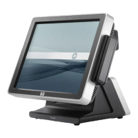
AC adapter, 130W
Includes AC power cord. 591693-001
Power cords
For use in:
Afghanistan, Albania, Algeria, Andorra, Angola, Armenia, Austria, Azer-
baijan, Azores (Portugal), Belarus, Belgium, Benin, Bolivia, Bosnia and
Herzegovina, Bulgaria, Burkina, Burma (Myanmar), Burundi, Cameroon,
Canary Islands (Spain), Cape Verde, Central African Republic, Chad, Como-
ros, Congo, Croatia, Czech Republic, Djibouti, East Timor, Egypt, Equatorial
Guinea, Eritrea, Estonia, Ethiopia, Finland, France, French Guiana, French
Polynesia, Gabon, Georgia, Germany, Greece, Greenland, Guadeloupe,
Guinea, Hungary, Iceland, Indonesia, Iran, Iraq, Ivory Coast, Kazakhstan,
South Korea, Kyrgyzstan, Latvia, Lebanon, Libya, Lithuania, Luxembourg,
Macedonia, Madagascar, Madeira Islands, Mali, Martinique, Mauritania, May-
otte, Miquelon, Moldova, Monaco, Mongolia, Morocco, Mozambique, Nether-
lands, New Caledonia, Niger, Norway, Poland, Portugal, Reunion, Romania,
Russia, Rwanda, Saint Pierre and Miquelon, San Marino, Sao Tome and Princ-
ipe, Senegal, Serbia and Montenegro, Slovakia, Slovenia, Somalia, Spain,
Svalbard, Sweden, Syria, Tahiti, Tajikistan, Togo, Tunisia, Turkey, Turkmeni-
stan, Ukraine, Uzbekistan, Vatican City, Vietnam, Wallis and Futuna, Western
Sahara, Zaire
602046-001
Argentina 602054-001
Australia 605052-001
Brazil 602057-001
People’s Republic of China 602053-001
Denmark 602049-001
India 602059-001
Israel 602055-001
Chile, Italy, and Uruguay 602048-001
Japan 602051-001
Japan - Domestic 602061-001
American Samoa, Anguilla, Antigua and Barbuda, Aruba, Bahamas, Barbados,
Belize, Bermuda, Cacaos and Turks Islands, Canada, Cayman Islands, Colom-
bia, Costa Rica, Cuba, Dominican Republic, Ecuador, El Salvador, Guam,
Guatemala, Guyana, Haiti, Honduras, Jamaica, Laos, Liberia, Marshall
Islands, Mexico, Micronesia, Midway Islands, Netherlands Antilles, Nicara-
gua, Northern Marianna Islands, Palau, Panama, Paraguay, Peru, Puerto Rico,
Saudi Arabia, Suriname, Trinidad and Tobago, Turks and Cacaos Islands,
United States, Venezuela, Virgin Islands, Wake Island
602045-001
South Africa 602058-001
South Korea 602062-001
Switzerland 602050-001
Taiwan 602060-001
Thailand 602056-001
The United Kingdom 602047-001
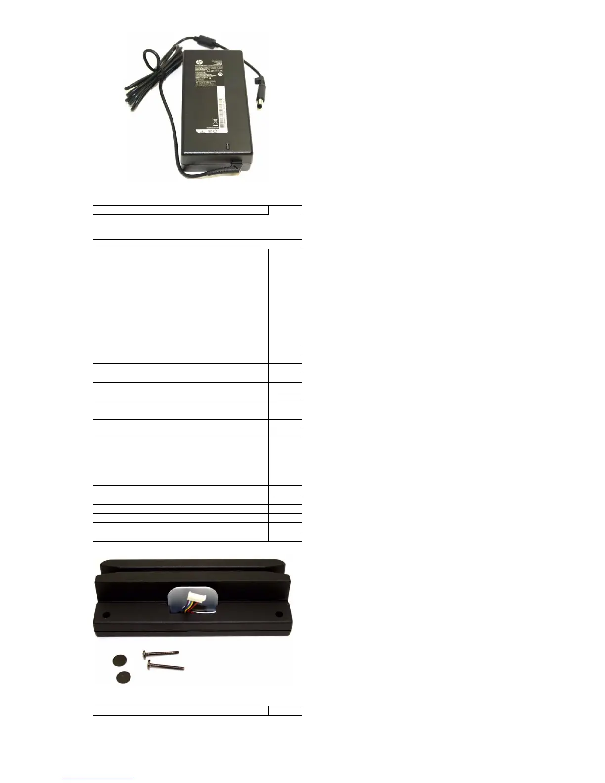
Magnetic strip reader (MSR)
Entire assembly, including screws and screw covers 591694-001
 Loading...