List the type and size of the tools that would typically be used to disassemble the product to a point where components
and materials requiring selective treatment can be removed.
3.1 List the basic steps that should typically be followed to remove components and materials requiring selective treatment:
1. System Battery - Remove the top cover and locate the standup card in back pci card slot bay next to the chassis wall.
Remove the board by pulling the front CPU drawer out ~ 3 inches then unscrewing the PCA's two blue finger screws
located on both ends of the PCA. Use a medium flat head screwdriver or fingers to remove the battery and dispose of
properly.
2. Megacell - Some models, remove the battery from the holder and disconnect cable from PCA.
3. Capacitors=>2.5CM - Remove the power supplies from the system. With a #2 Philips screw driver, remove the screws
securing the top cover, then locate the capacitors and pry from the PCB with a medium flat head screw driver and
dispose of properly.
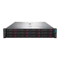
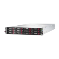
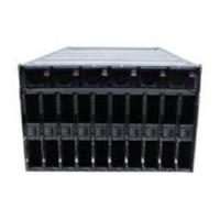
3.2 Optional Graphic. If the disassembly process is complex, insert a graphic illustration below to identify the items
contained in the product that require selective treatment (with descriptions and arrows identifying locations).
Attachment 1, 2 – System Coin Battery location
Attachment 3 – Megacell location
Attachment 4 to 8 - Capacitor location by model number of supply