005 Sensor Test Sequence
5-6 Diagnostic Tests June 1999
005 Sensor Test Sequence
1 Go to: 005
2 Press: READY to run the test. The code for the first sensor (i.e., “0-0” or “0-1”)
appears on the display, confirming that the sensor is working properly.
3 Press: READY to advance to the next sensor. The display changes, showing the code
for the next sensor as outlined in Table 5-2, “Sensor Test Displays”, below.
4 To check a specific sensor, press READY repeatedly until the code on the display cor-
responds to the sensor you want to check. Manually activate the sensor. Confirm that
the display changes when you activate the sensor. Refer to “Sensor and Switch Loca-
tions” on page 1-11 for sensor locations.
5 Press: STOP to exit.
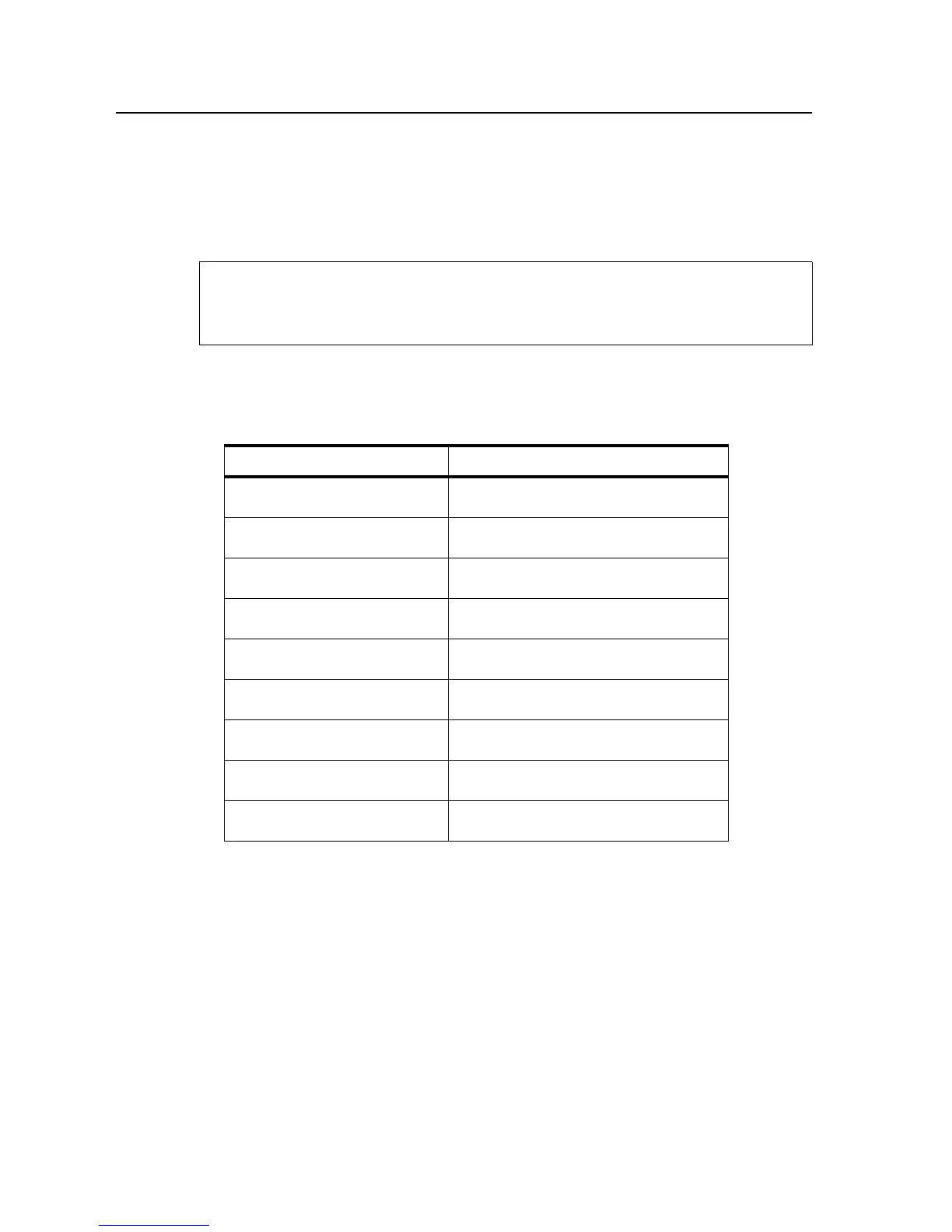
Table 5-2. Sensor Test Displays
Sensor Description Display
Upper paper cassette 0-0: Cassette full
0-1: Cassette empty
Lower paper cassette 1-0: Cassette full
1-1: Cassette empty
Paper timing sensor 2-0: No paper at sensor location
2-1: Paper at sensor
Paper exit sensor 3-0: No paper at sensor location
3-1: Paper at sensor
Paper full sensor 4-0: Tray empty
4-1: Tray full
Jogging sensor, front 5-0: Tray in front position
5-1: Error – tray in rear position
Jogging sensor, rear 6-0: Tray in rear position
6-1: Error – tray in front position
PC seam sensor 7-0: Active
7-1: Not active
Developer interlock 8-0: Developer unit in place
8-1: Developer unit not in place
No paper moves through the machine, so indications of
“No paper at sensor location” are normal.
Note