Circuit Board Settings
6-30 Wiring Diagrams and Electrical Data June 1999
Circuit Board Settings
Several of the circuit boards in the printer have jumpers and/or DIP switches used to con-
trol the functionality of the board. These settings are described the following section.
Signal Interface Board Settings
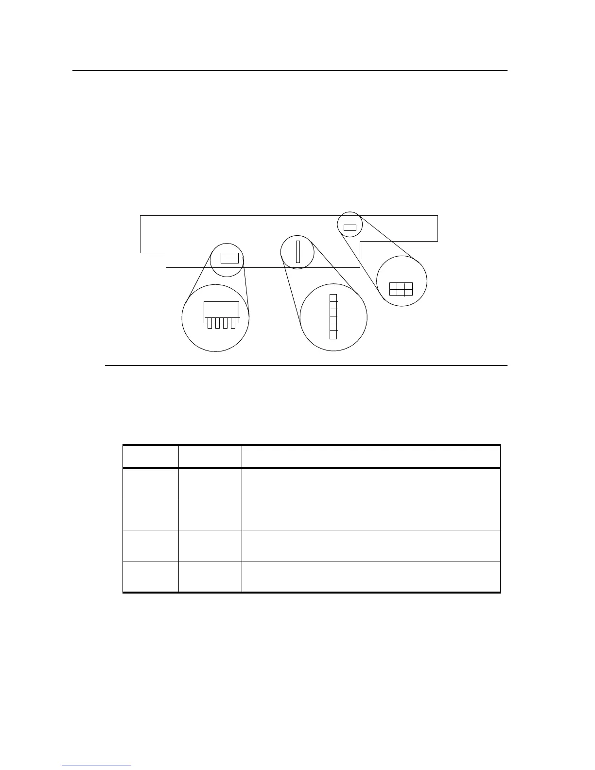
The signal interface board has both jumpers and DIP switches used to control host inter-
face interactions.
Figure 6-8. Signal Interface Board Jumper/Switch Locations
In general, the four jumpers on the signal interface board should remain as set at the fac-
tory. The jumpers control the following:
The four DIP switches on the signal interface board should be changed based on the host
interface being used.
For an RS-232C host interface: the DIP switches may be set in either direction; they
have no effect on an RS-232C interface.
Table 6-11. Signal Interface Board Jumper Settings
Jumper Direction Description
JP1 b-c
a-b
Baud rate crystal oscillator on IGS board 3.6854 MHz
Baud rate crystal oscillator on IGS board 7.3728 MHz
JP2 d-e
e-f
Unsolicited status reports enabled after power-on-reset
Unsolicited status reports disabled after power-on-reset
JP3 g-h
No jumper
ERR (pin 32) error line output enabled
ERR (pin 32) error line output disabled
JP4 i-j
j-k
PE (pin 12) out of paper line enabled
PE (pin 12) out of paper line disabled
JP3
JP4
JP1
JP2
SW
1
2
3
4
A
B
C
D
E
F
G
H
K
J
I