Circuit Board Settings
June 1999 Wiring Diagrams and Electrical Data 6-31
For an RS-422 host interface: set all four DIP swiches to ON by raising them up away
from the printed circuit board.
Figure 6-9. RS-422 Host Interface DIP Settings
For a Centronics Parallel Host Interface: set all four DIP switches to OFF by pushing
them down toward the printed circuit board.
Figure 6-10. Centronics Parallel Host Interface DIP Settings
PCL Board Settings
The PCL board uses DIP switches to control the registration of prints. Change these set-
tings only if directed to do so when following TAG #807.
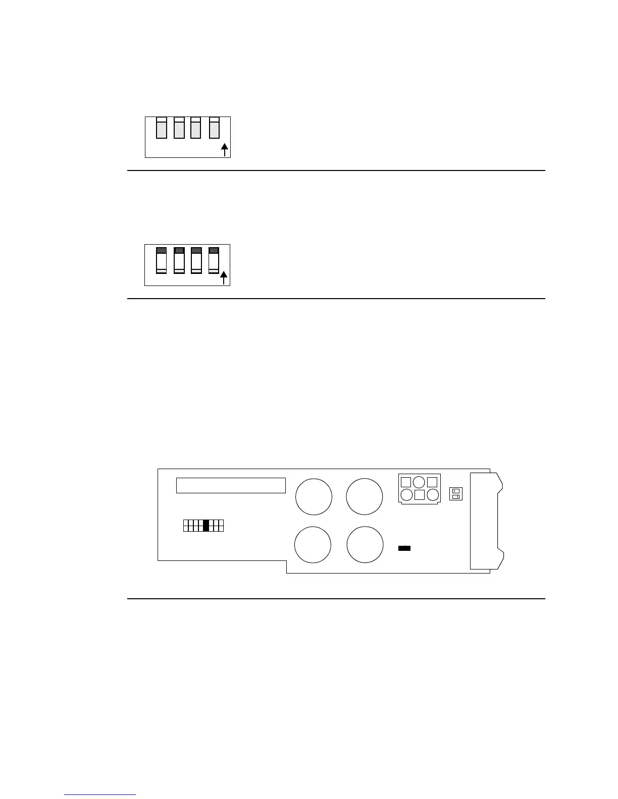
Printhead Circuit Board Settings
The printhead circuit board uses jumpers to match printhead characteristics to controller
characteristics. Do not change these jumper settings; they should remain as set at the fac-
tory.
Figure 6-11. Printhead Circuit Board Jumper/Switch Locations
ON
12 34
ON
1234
•
•
•
•
•
•
•
•
•
•
•
••
••
•
•
•
•
•
•
J30
J29
SW1
JP2
J28
JP1
18