List of figures
Figure 1-1. Model and serial number information ................................................................9
Figure 1-2. Sample label ....................................................................................................10
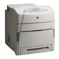
Figure 1-3. Front view, HP Color LaserJet 5500 models ..................................................11
Figure 1-4. Back view, HP Color LaserJet 5500 models ...................................................11
Figure 1-5. Front view, HP Color LaserJet 5550 models ..................................................12
Figure 1-6. Back view, HP Color LaserJet 5550 models ...................................................12
Figure 1-7. EMI statement for Korea .................................................................................38
Figure 1-8. VCCI statement for Japan ...............................................................................38
Figure 3-1. Space requirements (printer only) ...................................................................52
Figure 3-2. Package contents for HP Color LaserJet 5500, 5500n, and 5500dn .............53
Figure 3-3. Package contents for HP Color LaserJet 5550, 5550n, and 5550dn .............54
Figure 3-4. Parallel port connection (HP Color LaserJet 5500 models) ............................75
Figure 3-5. Parallel port connection (HP Color LaserJet 5550 models) ............................75
Figure 3-6. USB connection ..............................................................................................76
Figure 3-7. Auxiliary connection ........................................................................................76
Figure 3-8. Direct to network connection ...........................................................................77
Figure 3-9. Network print server connection .....................................................................77
Figure 3-10. Peer to peer connection (direct to network) ....................................................78
Figure 3-11. Peer to peer connection (parallel) ...................................................................78
Figure 4-1. ETB total page count according to average job length .................................113
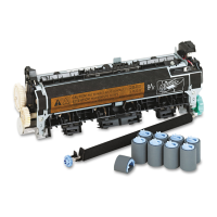
Figure 4-2. Location of supplies ......................................................................................114
Figure 5-1. Basic system operation .................................................................................135
Figure 5-2. Engine control system ...................................................................................137
Figure 5-3. DC controller circuit .......................................................................................138
Figure 5-4. Motors and fans ............................................................................................140
Figure 5-5. Fuser power supply circuit ............................................................................141
Figure 5-6. Heater temperature control circuit .................................................................142
Figure 5-7. High-voltage power supply circuit .................................................................144
Figure 5-8. Low-voltage power supply circuit ..................................................................145
Figure 5-9. Formatter system ..........................................................................................146
Figure 5-10. Laser/scanner system ...................................................................................150
Figure 5-11. Scanner motor control circuit ........................................................................151
Figure 5-12. Image formation system ................................................................................152
Figure 5-13. Image formation process ...............................................................................154
Figure 5-14. Print cartridge ................................................................................................155
Figure 5-15. Memory tag ...................................................................................................156
Figure 5-16. Toner level detection .....................................................................................158
Figure 5-17. Developing cylinder disengaging ..................................................................159
Figure 5-18. ETB unit .........................................................................................................160
Figure 5-19. Primary exposure ..........................................................................................161
Figure 5-20. Primary charging ...........................................................................................162
Figure 5-21. Laser beam exposure ...................................................................................162
Figure 5-22. Development block ........................................................................................163
Figure 5-23. Attaching the paper to the ETB .....................................................................164
Figure 5-24. Toner transfer ................................................................................................165
Figure 5-25. Separation .....................................................................................................165
ENWW xv
 Loading...