When replacing the system board, be sure that the following components are removed from the defective
system board and installed on the replacement system board:
●
Memory module (see
Memory module on page 57)
●
WLAN module (see
WLAN module on page 54)
●
Processor (see
Processor on page 92)
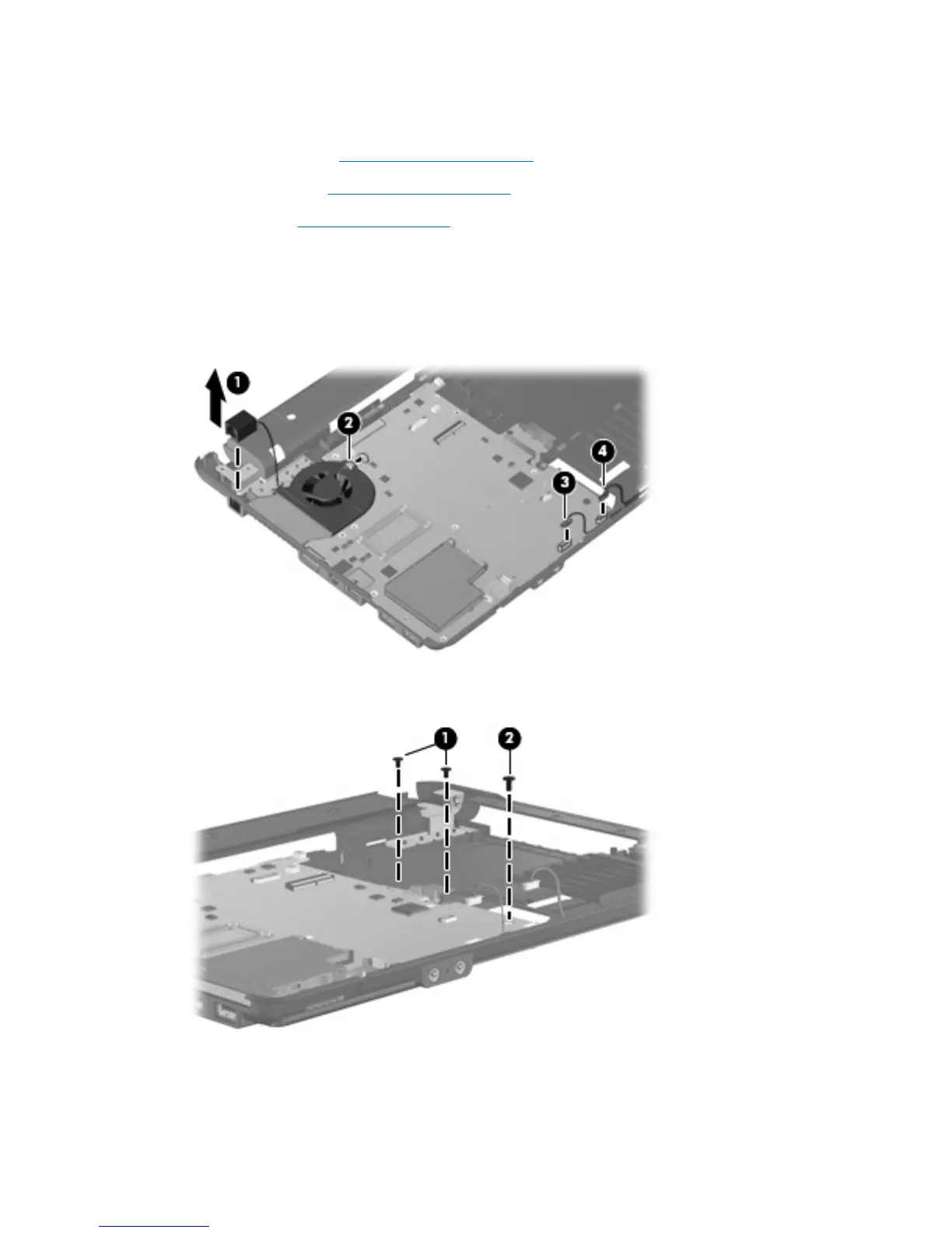
Remove the system board:
1. Disconnect the Bluetooth module cable (1), and the fan cable (2) from the system board.
2. Disconnect the USB connector module cable (3) from the system board, and remove the RJ-11
connector (4) from the base enclosure clip.
3. Remove the two Phillips 2.0x4.0 screws (1) and the Torx T8M2.5×6.0 screw (2) from the system
board.
4. Flex the left side of the base enclosure until the external monitor connector (1) and the heat sink
(2) are clear of the openings in the base enclosure.
5. Lift the rear edge of the system board (3) until it rests at an angle.
84 Chapter 4 Removal and replacement procedures