Table
A-1.
Test Equipment Required
TYPE
Oscilloscope
RMS Voltmeter
Multimeter
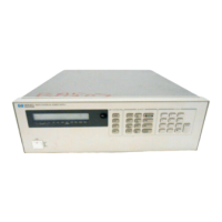
Electronic Load
Load Re8istor(For high current
range)
Current Sampling Resistor
Variable Voltage Auto Transformer
REQUIRED CHARACTERISTICS
Sensitivity : 2 mV
Bandwidth : 10 MHz/100 MHz
Input : Differentia), 50 ohm, 100 ohm
True rms, 10 MHz bandwidth
Sensitivity : 1 mV
Accuracy : 5%
Resolution : 100 nV
Accuracy : 0.0035%
Voltage Range : 240 Vdc
Current Range : 10 Adc
Open and short switches
Transient on/off
2.6 ohm 50 W, 13.3 ohm 50 W, 120 ohm
50W
0.1 ohm
0.1%
low, 1 ohm 1% 10 W
Range : 85-130 and 200-260 Volts
USE
P
P
P.A
P,A
P
P.A
P
RECOMMENDED MODEL
HP54600A
HP3400A
HP3456A
HP6063A
P
=
Performance testing
A =
Calibration adjustments.
Constant Voltage(CV) Test
The measuring device must
be
connected
as
close
to the
output
terminals
as
possible when measuring
the
output impedance,
transient response, regulation,
or
ripple
of the
power supply
in
order
to achieve valid measurements.
A
measurement made across
the
load includes
the
impedance
of the
leads
to the
load
and
such lead
lengths
can
have
an
impedance several orders
of
magnitude greater
than
the
supply output impedance, thus Invalidating
the
measure-
ment.
For all CV
tests
set the
output current
at
full rated output
to
assure
CV
operation.
Load Effect(Load Regulation)
Definition:
CV
Load Effect
is the
change
in dc
output voltage when
load resistance changes from open circuit
to
full load
or
from full load
to open circuit.
Test Parameters:
Measured Variable: Output Voltage
Expected Results: Less than 0.01
%
plus
2 mV
Test Procedure:
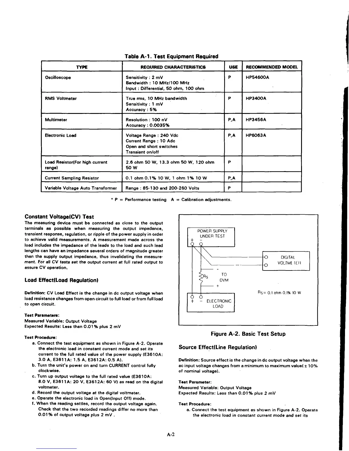
a. Connect
the
test equipment
as
shown
in
Figure A-2. Operate
the electronic load
in
constant current mode
and set its
current
to the
full rated value
of the
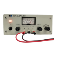
power supply (E3610A:
3.0
A,
E3611
A: 1.5 A,
E3612A:
0.5 A).
b. Turn
the
unit's power
on and
turn CURRENT control fully
clockwise.
c. Turn
up
output voltage
to the
full rated value (E3610A:
8.0
V.
E3611
A: 20 V,
E3612A:
60 V) as
read
on the
digital
voltmeter.
d.
Record
the
output voltage
at the
digital voltmeter.
e. Operate
the
electronic load
in
Opendnput
Off)
mode.
f.
When
the
reading settles, record
the
output voltage again.
Check that
the two
recorded readings differ
no
more than
0.01
% of
output voltage plus
2 mV .
POWER SUPPLY
UNDER TEST
+
-
2^^
\
DIGITAL
VOLTMt.
ILR
TO
DVM
6
ELECTRONIC
LOAD
Rs= 0.1 ohm
0.1%
10 W
Figure A-2. Basic Test Setup
Source EffectlLine Regulation)
Definition:
Source effect
is the
change
in dc
output voltage when
the
ac input voltage changes from
a
minimum
to
maximum value!
± 10%
of nominal voltage).
Test Parameter:
Measured Variable: Output Voltage
Expected Results: Less than 0.01% plus
2 mV
Test Procedure:
a. Connect
the
test equipment
es
shown
in
Figure A-2. Operate
the electronic load
in
constant current mode
and set its
A-2