4. Remove the battery (see Battery on page 48), and then remove the following components:
5. Remove the following components:
a. Memory module compartment cover (see
Expansion memory module on page 52)
b. Wireless module compartment cover (see
WLAN module on page 57)
c. Switch cover and keyboard (see
Switch cover and keyboard on page 69)
d. Display assembly (see
Display assembly on page 76)
e. Top cover (see
Top cover on page 85)
f. System board (see
System board on page 94)
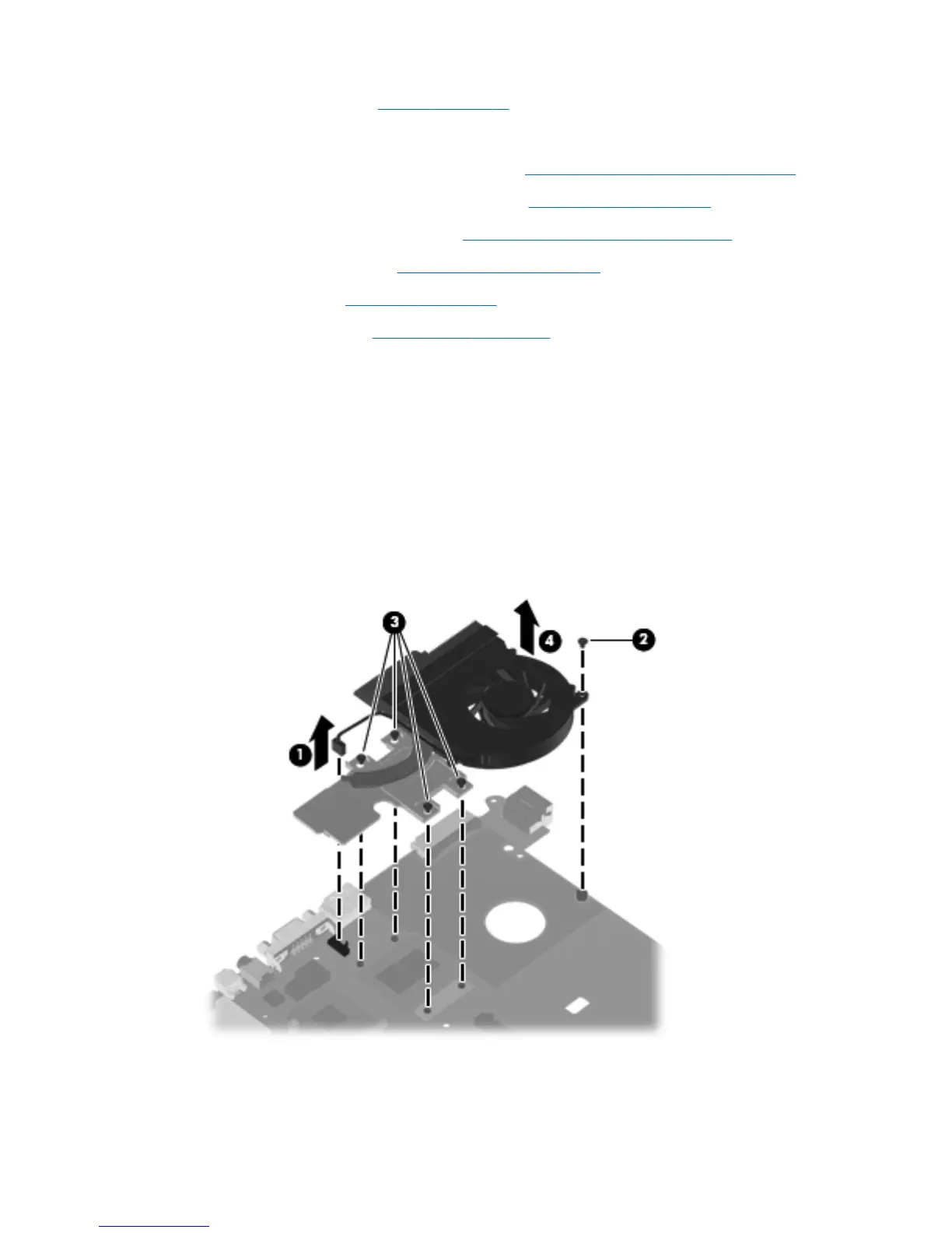
Remove the fan/heat sink assembly:
1. Turn the system board upside down, with the front toward you.
2. Disconnect the fan cable (1) from the system board.
3. Remove the Torx T8M2.0×5.0 screw (2) that secures the fan/heat sink assembly to the system
board.
4. Following the 1, 2, 3, 4 sequence stamped into the fan/heat sink assembly, loosen the four
captive screws (3) that secure the fan/heat sink assembly to the system board.
5. Remove the fan/heat sink assembly (4).
ENWW Component replacement procedures 99
 Loading...