System board connections
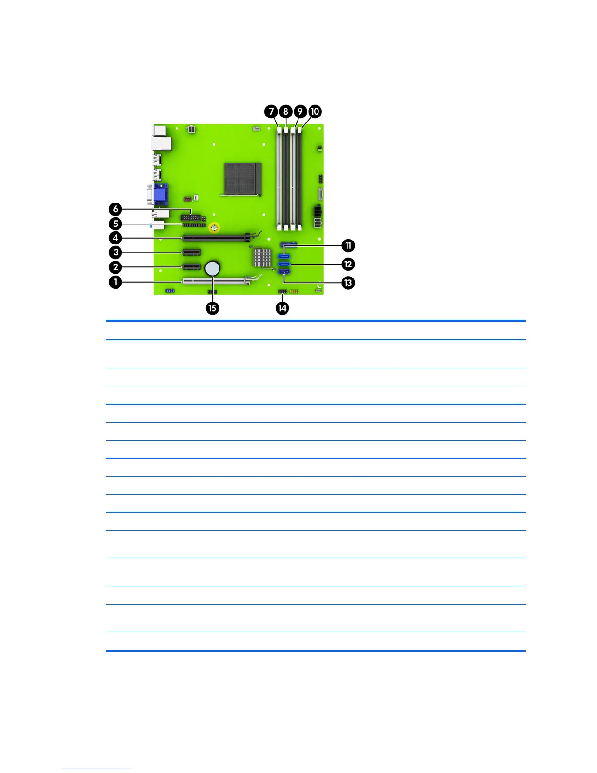
Refer to the following illustration and table to identify the system board connectors for your model.
No. System Board Connector System Board Label Color Component
1 PCI Express x16 downshifted
to a x4
X4PCIEXP white Expansion Card
2 PCI Express x1 X1PCIEXP2 black Expansion Card
3 PCI Express x1 X1PCIEXP1 black Expansion Card
4 PCI Express x16 X16PCIEXP black Expansion Card
5 Parallel Port PAR black Optional Parallel Port
6 Serial Port COMB black Optional Second Serial Port
7 DIMM4 (Channel A) DIMM4 white Memory Module
8 DIMM3 (Channel A) DIMM3 black Memory Module
9 DIMM2 (Channel B) DIMM2 white Memory Module
10 DIMM1 (Channel B) DIMM1 black Memory Module
11 SATA 3.0 SATA2 light blue Any SATA Device other than the
Primary Hard Drive
12 SATA 3.0 SATA1 light blue Any SATA Device other than the
Primary Hard Drive
13 SATA 3.0 SATA0 dark blue Primary Hard Drive
14 USB 2.0 MEDIA black USB 2.0 Device, such as a USB 2.0
Media Card Reader
15 Battery BAT black Battery
System board connections 13
 Loading...