16
Appendix
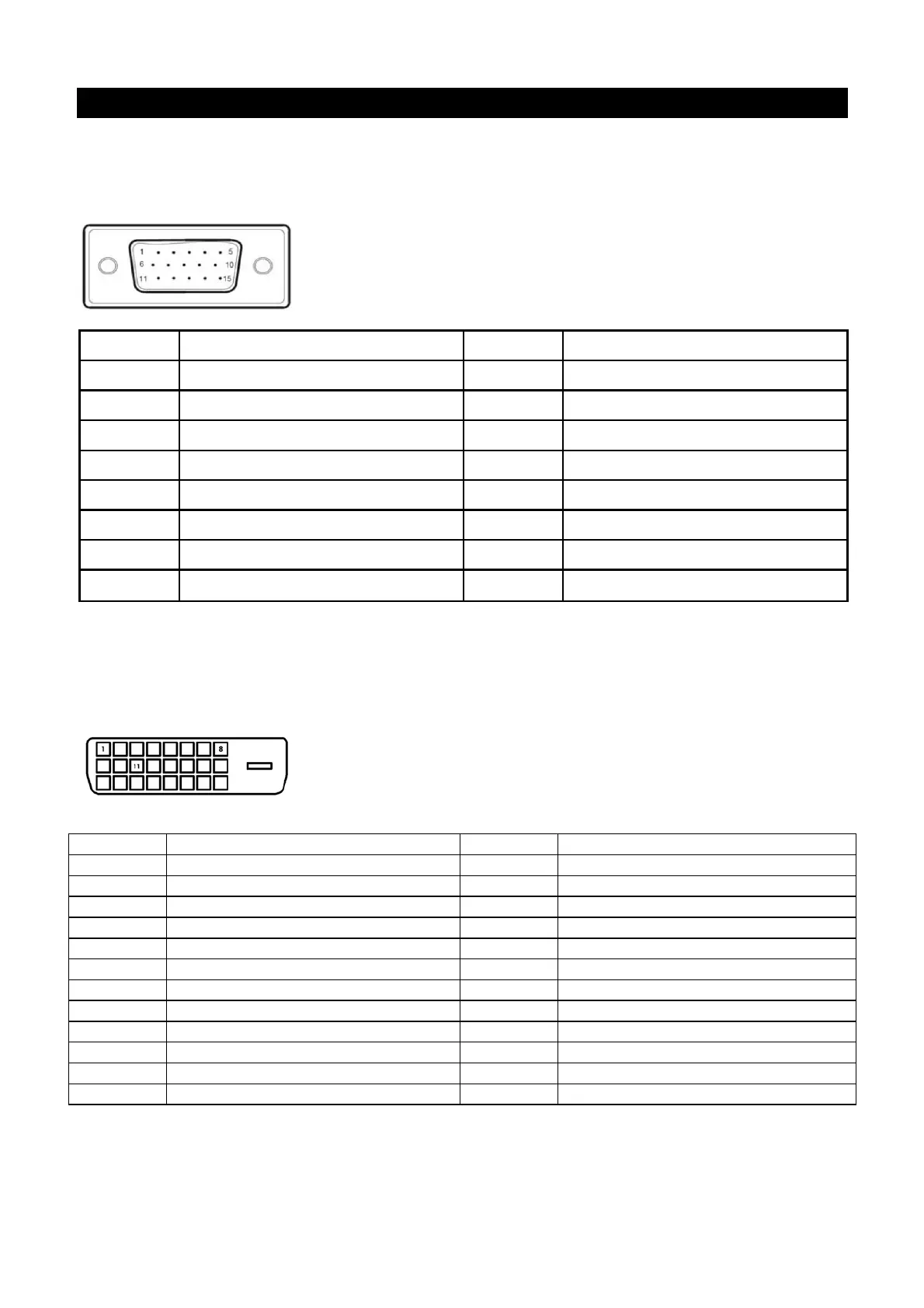
Connector pin assignment
• 15 pin color display signal cable:
PIN No. Description PIN No. Description
1. Red 9. +5V
2. Green 10. Logic ground
3.
Blue
11.
Monitor ground
4.
Monitor ground
12.
DDC-serial data
5. DDC-return 13. H-sync
6. R-ground 14. V-sync
7. G-ground 15. DDC-serial time sequence
8. B-ground
24 pin DVD-D display signal cable:
Pin No. Description Pin No. Description
1 TMDS Data 2 - 13 TMDS Data 3 +
2 TMDS Data 2 + 14 +3.3/+5V Power (from PC)
3 TMDS Data 2 / 4 Shield 15 Ground (Return for +5V)
4 TMDS Data 4 - 16 Hot Plug Detect
5 TMDS Data 4 + 17 TMDS Data 0 -
6 DDC Clock 18 TMDS Data 0 +
7 DDC Data 19 TMDS Data 0 / 5 Shield
8 No Connect 20 TMDS Data 5 -
9 TMDS Data 1 - 21 TMDS Data 5 +
10 TMDS Data 1 + 22 TMDS Clock Shield
11 TMDS Data 1 / 3 Shield 23 TMDS Clock +
12 TMDS Data 3 - 24 TMDS Clock -
 Loading...