30 Chapter 2 - Removal and replacement Q1342-90910
Connector PCB Assembly
1 Remove the following assemblies:
z Toner cartridge, media tray, and cable pod. See “Toner cartridge”
on page 15 through “Cable pod” on page 17.
z Left side, back, right side, and top covers. See “Left side cover”
on page 18 through “Top cover” on page 29.
2 Open the toner cartridge door.
3 Disconnect the laser scanner ribbon cable (at the laser/scanner
end), laser scanner wire harness, LED status panel wire harness,
and ECU ribbon cable.
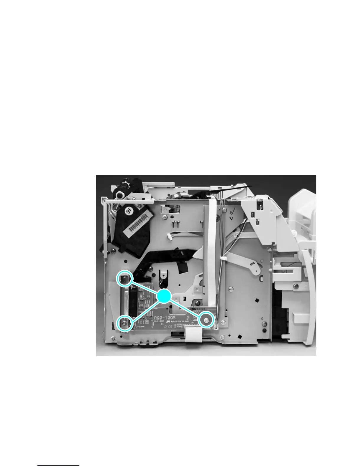
4 Remove the three connector PCB assembly mounting screws
(callout 1), and remove the assembly.
Figure 19. Remove the connector assembly
11
 Loading...