Removal and Replacement
Internal Assemblies
Internal Assemblies
Laser/Scanner Assembly
1. Remove the Printer Cover.
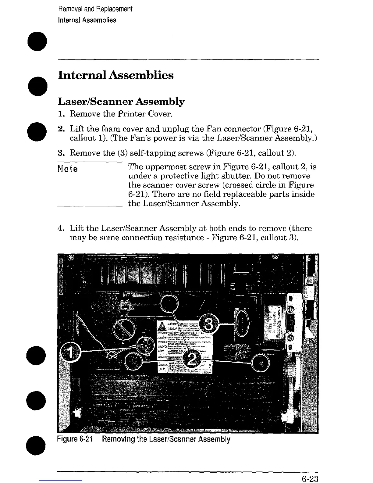
2. Lift the foam cover and unplug the Fan connector (Figure 6-21,
callout 1). (The Fan’s power is via the Laser/Scanner Assembly.)
3. Remove the (3) self-tapping screws (Figure 6-21, callout 2).
Note
The uppermost screw in Figure 6-21, callout 2, is
under a protective light shutter, Do not remove
the scanner cover screw (crossed circle in Figure
6-21). There are no field replaceable parts inside
the Laser/Scanner Assembly.
4. Lift the Laser/Scanner Assembly at both ends to remove (there
may be some connection resistance - Figure 6-21, callout 3).
Figure 6-21 Removing the Laser/Scanner Assembly
6-23
 Loading...