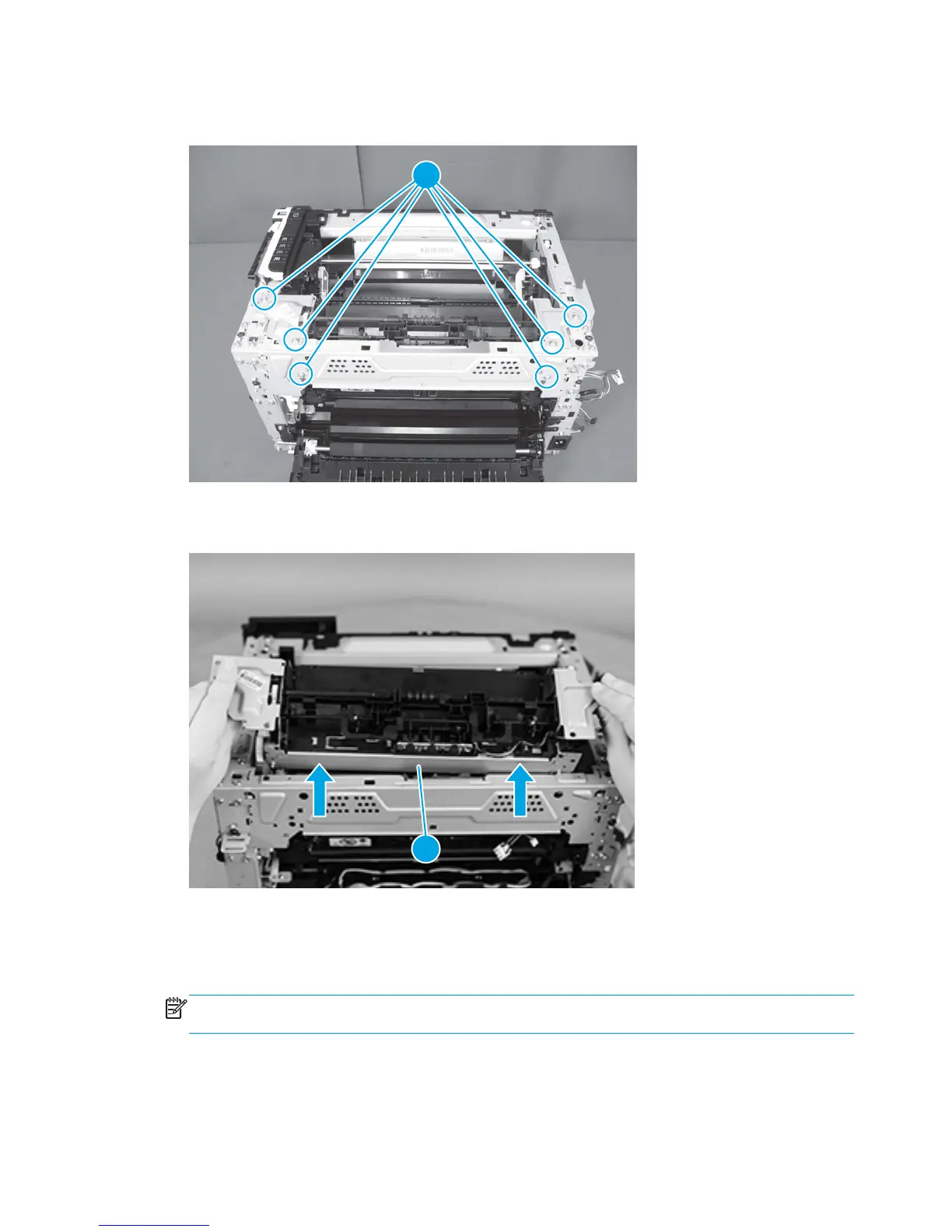
8. Remove six screws (callout 1).
Figure 1-80 Remove the fuser delivery assembly (8 of 9)
1
9. Lift the fuser delivery assembly to remove it (callout 1).
Figure 1-81 Remove the fuser delivery assembly (9 of 9)
1
Reinstall the fuser delivery assembly
●
When reinstalling the fuser delivery assembly, be sure the drive cam (callout 1) for fuser pressure
release is positioned as shown below and meets the matching fuser part (callout 2).
NOTE: These parts should be aligned if the product was turned on and off before removing the fuser
delivery assembly.
58 Chapter 1 Removal and replacement ENWW
 Loading...