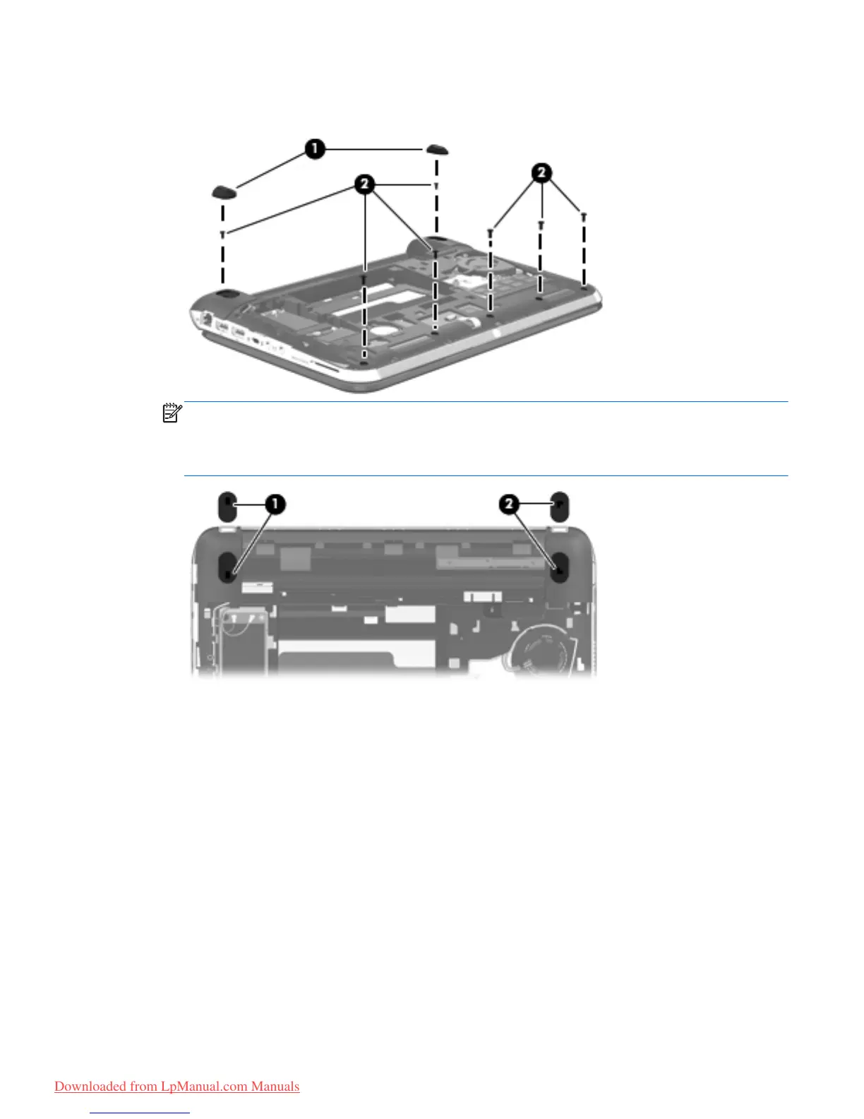
5.
Remove the seven Phillips PM2.0×5.0 screws (2) that secure the top cover and the corner covers
to the base enclosure.
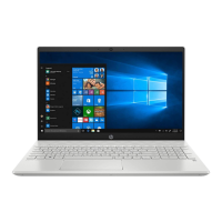
NOTE: The rubber feet are notched differently. The rubber foot (1) that fits on the left side has a
rectangular alignment notch. The rubber foot (2) that fits on the right side has an “L”-shaped
alignment notch. When installing the rubber feet, align them according to the side of the computer
on which they should be installed.
Component replacement procedures
69
Downloaded from LpManual.com Manuals