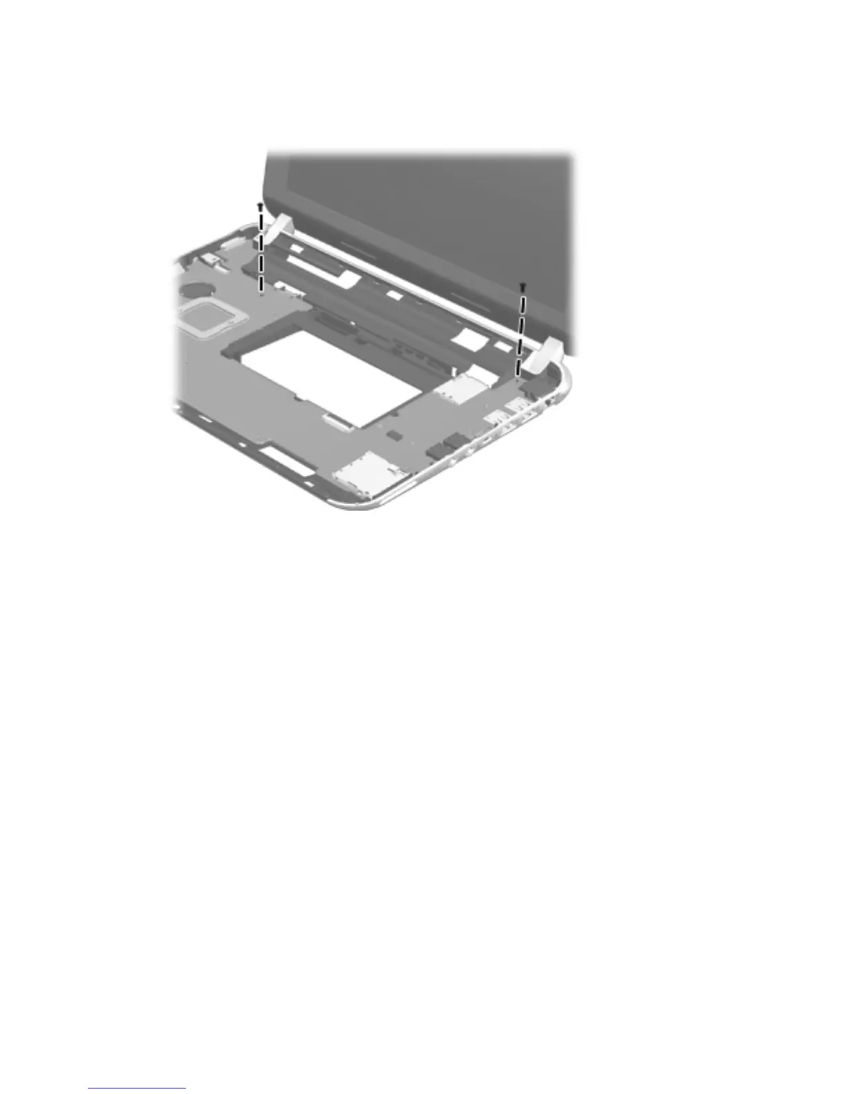
Remove the system board:
1. Remove the two Phillips PM2.0×5.7 screws that secure the system board to the base enclosure.
2. Release the power connector (1) from the clip built into the base enclosure.
3. Flex the right side of the base enclosure (2) until the jacks and ports on the right side of the
system board are clear of the openings in the base enclosure.
4. Lift the right side of the system board (3) until it rests at an angle.
56 Chapter 4 Removal and replacement procedures