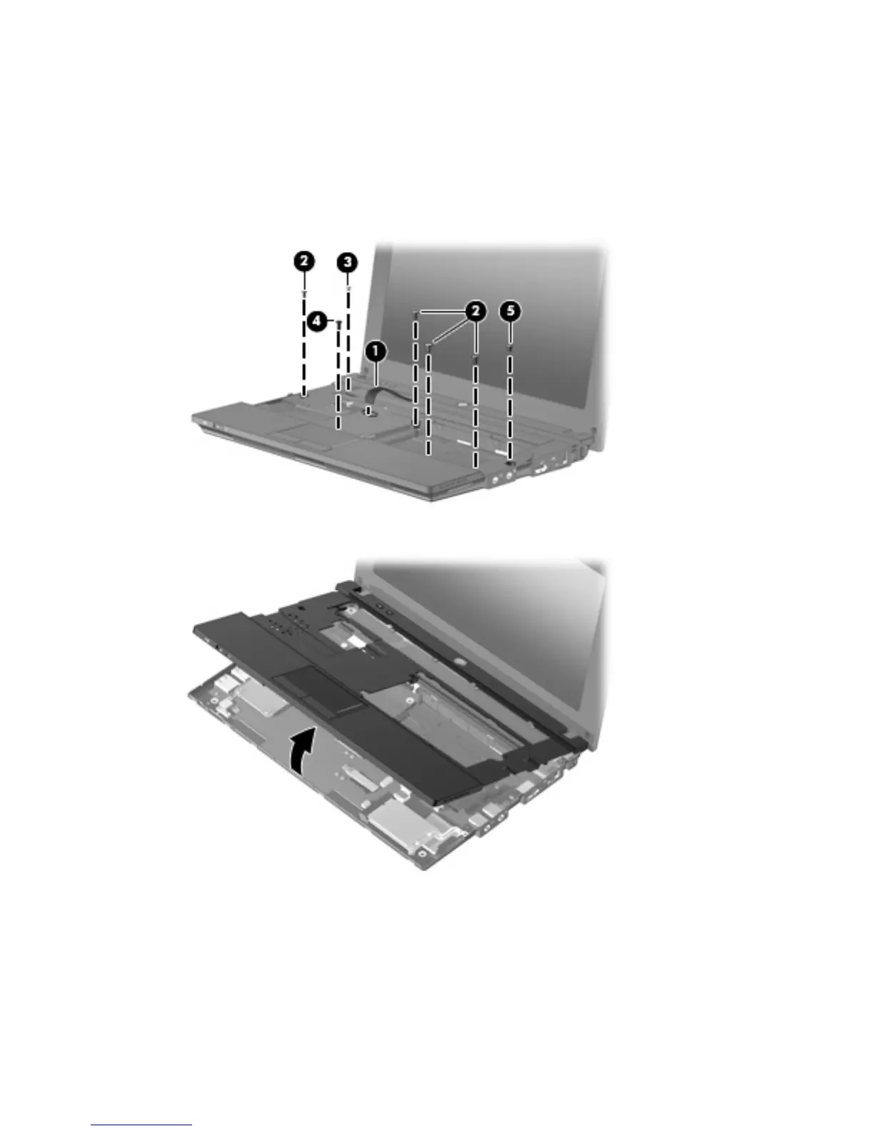
7. Remove the following screws that secure the top cover to the base enclosure:
●
(2) - 4 Phillips BP2.0×6.0
●
(3) - 1 Phillips BP2.0×7.0
●
(4) - 1 Phillips SP2.0×2.0
●
(5) - 1 Phillips BP2.0×2.0
8. Lift the outside edge of the top cover, and swing it up.
9. Release the ZIF connector (1) to which the TouchPad button board cable is connected, and
disconnect the cable (2) from the system board.
Component replacement procedures 45
 Loading...