EasyManua.ls Logo

HP MSM720 User Manual

HP MSM720
6 pages
To Next Page IconTo Next Page
Page #1 background imageLoading...
Page #1 background image
HP MSM720 Controllers Quickstart
This Quickstart shows you how to install the MSM720 Controllers. This information applies to the MSM720 Access Controller (J9693A, J9695A) and the MSM720
Premium Mobility Controller (J9694A, J9696A). These products are hereafter referred to as controller. The controller works with HP access points to deliver a
high-performance networking solution. For additional installation information, and instructions on how to initially configure the controller, see the HP MSM720
Controllers Installation Guide, available at www.hp.com/support/manuals.
Hardware overview
MSM720 front panel
1: Power, Fault, and Locator LEDs
2: LED Mode select button and Mode Indicator LEDs
3: Four 10/100/1000 access network ports
4: Two dual-personality Internet network ports
5: Console port
6: Test LED
7: Reset and Clear buttons
8: Port LEDs: Link (left) and Mode (right)
Package contents
Controller, power adapter and cord, console cable, four mounting brackets,
eight bracket screws, four rubber feet, and documentation.
LEDs
There are three types of LEDs: Status LEDs (labeled 1 and 6 in the graphic),
Port LEDs (8), and Port LED Mode indicators (2).
Reset and Clear buttons
The Reset and Clear buttons are accessible (with a paper clip) on the
controller front panel (labeled 7 in the image to the left).
To reset the controller, either power cycle it or press and release the Reset
button.
To reset the controller to factory defaults, press and quickly release the Reset
button, and then immediately press and hold the Clear button until the LEDs
above the Clear button flash three times.
Ports
Controller console port: A standard serial port with an RF-45 connector. To
connect to a computer, use the supplied DB-9 to RJ-45 console cable.
Access network: Four auto-sensing 10/100/1000 Base-T ports with the
Auto-MDX feature. You can use either straight-through or crossover
twisted-pair cables to connect network devices to the controller.
Internet network: Two dual personality ports for either 10/100/1000 Base-T
RJ-45(Auto-MDX) uplinks or optional SFP slots for fibre uplinks.
1 2
7
3
5 6 8
4
5998-7941_QS_MSM720_2015-06-05.fm Page 1 Wednesday, June 10, 2015 2:01 PM

Other manuals for HP MSM720

Question and Answer IconNeed help?

Do you have a question about the HP MSM720 and is the answer not in the manual?

HP MSM720 Specifications

General IconGeneral
BrandHP
ModelMSM720
CategoryController
LanguageEnglish

Summary

Hardware Overview

MSM720 Front Panel Components

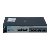
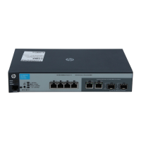
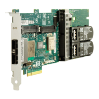
Identifies and describes the numbered components of the MSM720 controller's front panel.

Package Contents List

Lists the items included with the HP MSM720 controller.

LED Types Overview

Introduces the different types of LEDs on the controller and their general functions.

Reset and Clear Buttons

Reset and Factory Reset Procedures

Details how to perform a normal reset and a factory default reset using the buttons.

Ports Description

Controller Console Port

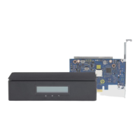
Explains the function and connection of the controller's serial console port for management.

Access Network Ports

Details the four auto-sensing 10/100/1000 Base-T network ports for connectivity.

Internet Network Ports

Describes the two dual-personality ports supporting RJ-45 or SFP for network uplinks.

Important Information Before Installing

Country of Use Selection

Explains the importance of selecting the correct country for compliant wireless channel operation.

Static Electricity Precautions

Provides essential procedures to prevent damage from static electricity during handling and installation.

Controller Specifications

Details environmental, physical, and safety specifications for the controller unit.

Installation Process

Prepare Installation Site

Outlines prerequisites for preparing the installation site, including cabling and location.

Verify Controller Self-Test

Explains how to verify the controller passes its initial self-test after power-up.

Controller Mounting Methods

Rack or Cabinet Mounting

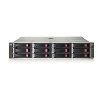
Provides instructions for mounting the controller in a standard 19-inch telco rack or cabinet.

Wall Mounting Procedure

Guides on mounting the controller securely on a wall or wood surface, noting port orientation.

Additional Installation Options

Horizontal Surface Installation

Explains how to attach rubber feet and place the controller on a horizontal surface.

LED Status Indicators Explained

Status LED Descriptions

Details the meaning of the Power, Fault, and Locator status LEDs during operation.

Port LED Descriptions

Explains the Link and Mode LEDs for RJ-45 and SFP ports and their indications.

Port Mode LED Operation

Speed and Activity Indicators

Explains how the Port Mode LED indicates port speed (10/100/1000 Mbps) and activity.

Regulatory and Compliance Information

FCC Class A Notice

States the FCC Class A compliance notice and conditions for operation in commercial environments.

Manufacturer and Representative Details

Provides manufacturer and local representative contact details for specific regions.

Manufacturing Date Encoding

Explains how to determine the manufacturing date from the product serial number format.

Related product manuals