4. Install four M3 metric guide screws in the lower holes on each side of the drive. HP has provided
four extra M3 metric guide screws on the front of the chassis, under the front bezel. The M3
metric guide screws are black. Refer to
Installing and Removing Drives on page 47 for an
illustration of the extra M3 metric guide screws location.
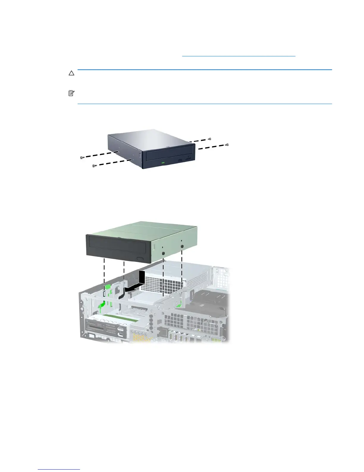
CAUTION: Use only 5-mm long screws as guide screws. Longer screws can damage the
internal components of the drive.
NOTE: When replacing the drive, transfer the four M3 metric guide screws from the old drive to
the new one.
Figure 5-22 Installing Guide Screws in the Optical Drive
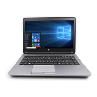
5. Position the guide screws on the drive into the J-slots in the drive bay. Then slide the drive
toward the front of the computer until it locks into place.
Figure 5-23 Installing the Optical Drive
Installing and Removing Drives 53