To remove the fan/heat sink assembly:
1. Turn the system board upside down, with the expansion port three and the external monitor port
toward you.
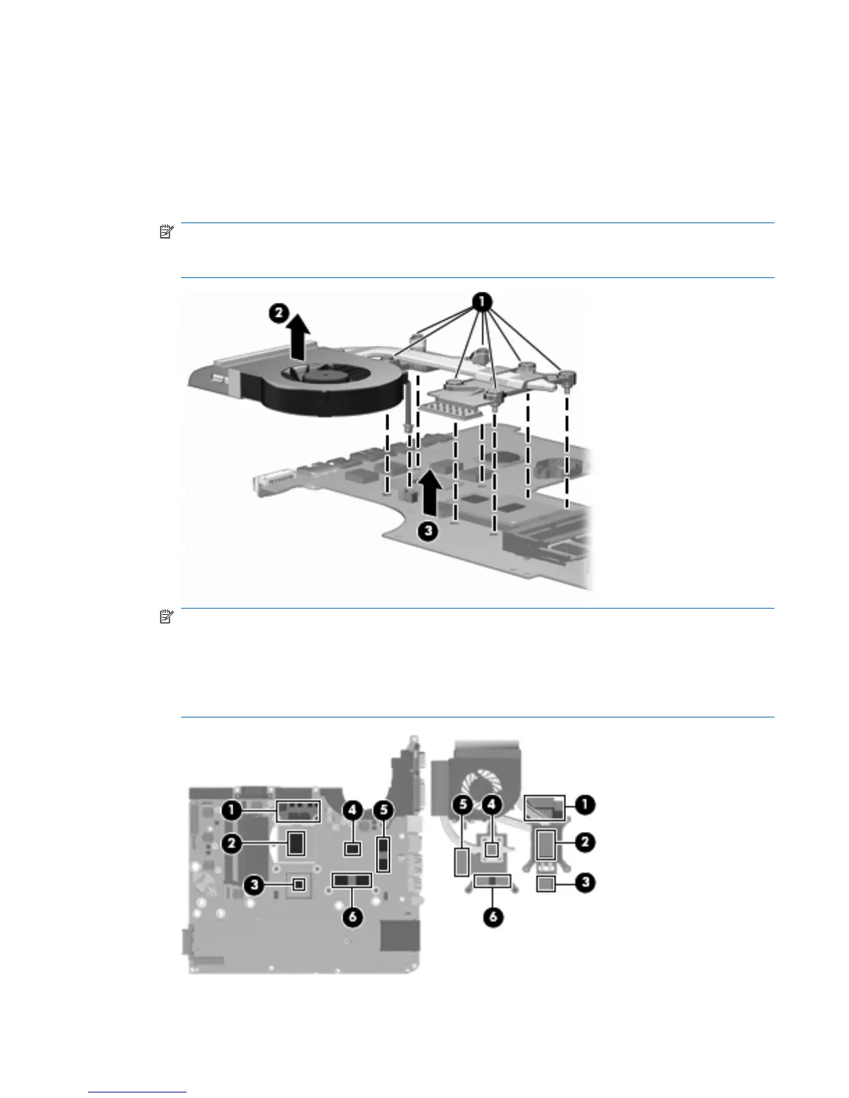
2. Loosen the seven captive screws (1) that secure the fan/heat sink assembly to the system board.
3. Remove the fan/heat sink assembly (2). Disconnect the fan cable (3) from the system board.
NOTE: Due to the adhesive quality of the thermal material located between the fan/heat sink
assembly and system board components, it might be necessary to move the fan/heat sink
assembly from side to side to detach the assembly.
NOTE: The thermal material must be thoroughly cleaned from the surfaces of the fan/heat sink
assembly and the system board each time the fan/heat sink assembly is removed. Thermal paste is
applied to the fan/heat sink assembly to correspond with components on the system board as
follows: the processor (1) and (2), the Northbridge chip (3) and (4), the graphics subsystem chip
(5) and (6), and three capacitors (7) and (8). Replacement thermal material is included with all
fan/heat sink assembly, system board, and processor spare part kits.
ENWW
Component replacement procedures
83
 Loading...