3. Disconnect the power from the computer by first unplugging the power cord from the AC outlet
and then unplugging the AC adapter from the computer.
4. Remove the battery (see
Battery on page 45).
5. Remove the following components:
a. Switch cover (see
Switch cover on page 47)
b. Keyboard (see
Keyboard on page 49)
c. Speakers (see
Speakers on page 56)
d. Palm rest (see
Palm rest on page 58)
e. WLAN cables (see
WLAN module on page 65)
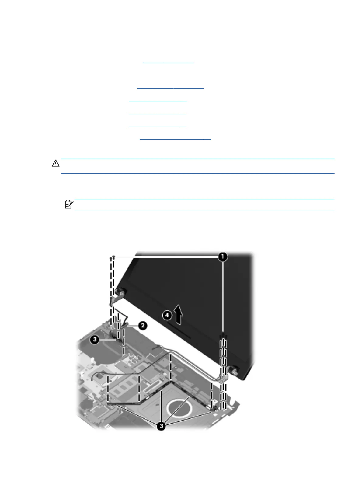
Remove the display assembly:
CAUTION: Support the display assembly when removing the following screws. Failure to support
the display assembly can result in damage to the display assembly and other computer components.
1. Remove the five T8 slotted-Torx M2.5×6.0 screws (1) that secure the display assembly to the
base enclosure.
NOTE: Your model of the computer have four screws.
2. Disconnect the display cable from the system board (2), and remove all cables from the routing
channels along the top cover (3).
3. Lift the display assembly (4) straight up and remove it from the base enclosure.
Component replacement procedures 79
 Loading...