3-3
Planning and Implementation for the Series 3500yl Switches
Planning Your PoE Configuration
Planning and
Implementation for the
Series 3500yl Switches
The table in this example configuration contains entries that show the PoE
power available for the 3500yl-24G-PWR.
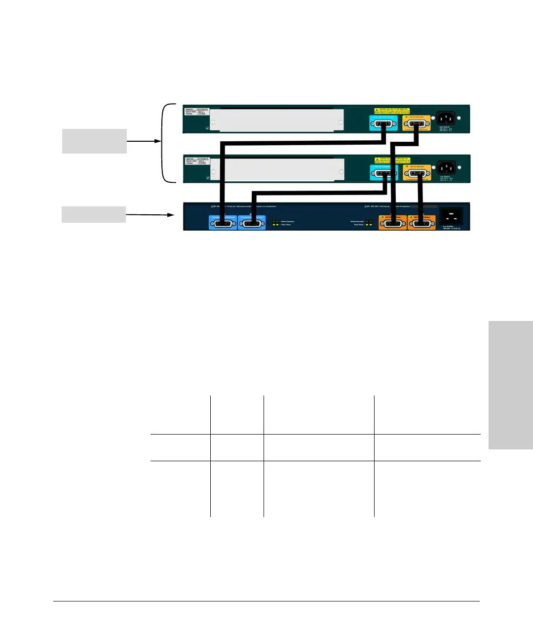
Figure 3-2. Example of two 3500yl-24G-PWR Switches connecting to a ProCurve
620 External and Redundant Power Supply (J8696A)
The same considerations for the mini-GBIC ports apply as in the previous
example.
As shown in this illustration, two 3500yl-24G-PWR switches can be supported
by one 620 RPS/EPS. This is a full redundant configuration. Both of the
switches can be supplied with power should either of their internal power
supplies fail. The 620 RPS/EPS can supply system power to keep the switch
powered on and PoE power to supply the attached PoE devices with power.
3500yl 24 port
switches
620 RPS/EPS
Source of
Power
Watts
Available
# of Ports Powered and
Average Watts/Port from
internal supply
# of Ports Powered and
Average Watts/Port from
external supply
Internal PoE
Power Supply
398 24 @ average 15.4 W each for
a total of 369.6 W
None
External PoE
Power Supply
(failed Internal
PoE Power
Supply)
388 None 24 @ average 15.4 W each
for a total of 369.6 W
 Loading...