4-17
Planning and Implementation for the Series 5400zl Switch
Planning Your PoE Configuration
Planning and
Implementation for the
Series 5400zl Switch
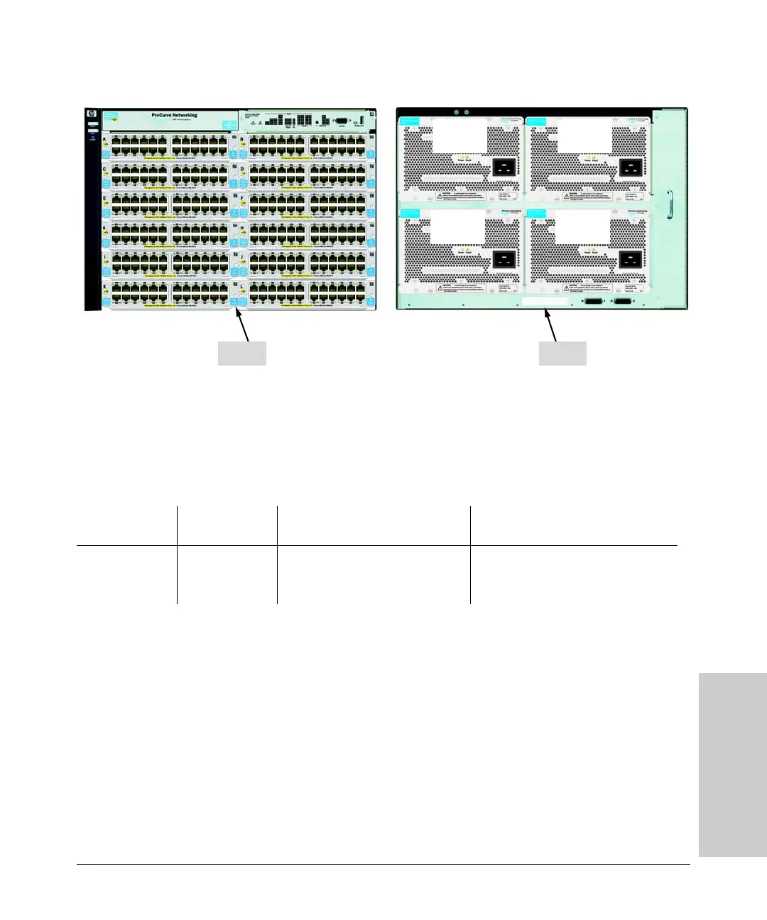
Figure 4-12. Example of a 5412zl with four power supplies, J8713A
This configuration is an example of four power supplies supplying 900 watts
each for a maximum of 3600 watts to a fully loaded chassis of 288 ports.
Therefore out of the total 288 available ports, 233 can be powered at 15.4 watts
each.
Or, two power supplies could be used to supply PoE power at 1800 watts and
the other two power supplies could be used as secondary power supplies. If
the two sets of power supplies are connected to different power sources, one
set of two could backup the other two in case of failure. With this option the
user must manage the PoE usage in order to maintain redundancy.
In this example the threshold command could be set at 50%, and if the switch
begins to use more than 1800 watts an event message would be logged.
Thereby allowing you to adjust the PoE load as required to obtain the best
power balance for your operation.
BackFront
900 Watts
for PoE
900 Watts
for PoE
900 Watts
for PoE
900 Watts
for PoE
Source of Power Watts Available # of Ports Powered and Average
Watts/Port
Redundant # of Ports Powered and
Average Watts/Port
Four Internal PoE
Power Supplies
(J8713A)
3600 (without
redundancy)
• 233 @ average 15.4 W each
• 288 @ average 7.0 W each
• 288 @ average 4.0 W each
• 116 @ average 15.4 W each
• 257 @ average 7.0 W each
• 288 @ average 4.0 W each
 Loading...