Component identification 12
Item Description
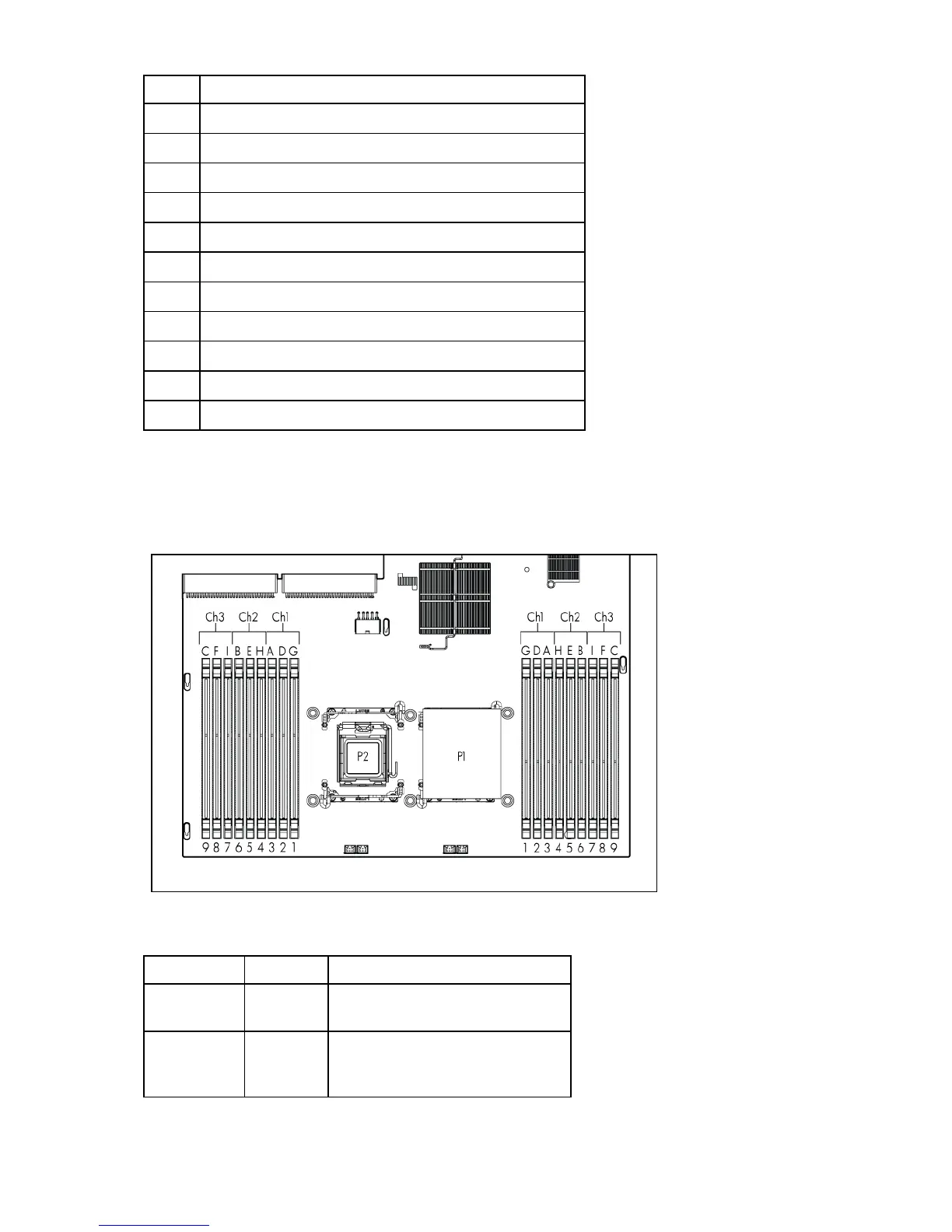
16 Processor 2 DIMM slots (9)
17 SD card slot
18 Internal USB connector
19 Hard drive power connector 1
20 Hard drive power connector 2
21 Power supply connector 1
22 System battery
23 Power supply connector 2
24 PCI power connector
25 TPM connector
26 PCIe riser board connectors (2)
DIMM slots
DIMM slots are numbered sequentially (1 through 9) for each processor. The supported AMP modes use
the letter assignments for population guidelines.
System maintenance switch
Position Default Function
S1 Off Off = iLO 2 security is enabled.
On = iLO 2 security is disabled.
S2 Off Off = System configuration can be
changed.
On = System configuration is locked.
 Loading...