15" LCD Color Monitor HP VP15
35
Panel Power Circuit
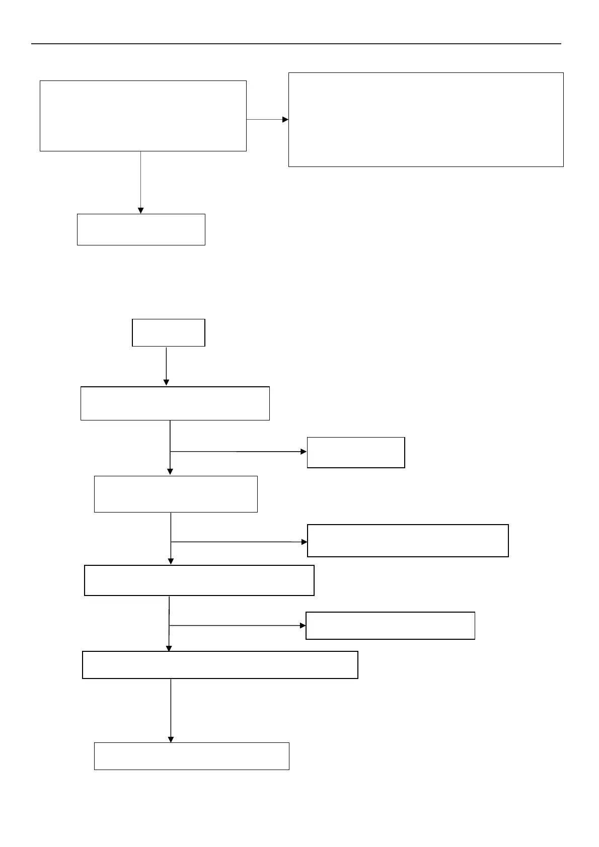
9.2.2 Power Board
1. No Power
Check CN101 PIN 23-24 should have
response from 0V to 5V When we
switch the power switch from on to off
Replace panel
Check the PPWR panel power relative circuit,Q706, Q704
In normal operation, when LED =green, R725
Should =5 V,
If PPWR no-response when the power switch
Turn on and turn off, re
lace the U401- TSUM16AWK -LF
OK
NG
Check AC line volt 110V or 220V
OK
Check AC line
Check the voltage of C905(+)
Check F901, bridge rectified circuit
Check start voltage for the pin3of IC901
Check R904-R906
Check the auxiliary voltage is between 10V-16V
Check IC901,T901, D901,D903
OK
OK
No power
NG
NG
NG
 Loading...