Hardware Management (Monitoring and Reporting)
Hardware Monitoring
Chapter 574
Fan Speed and Control
Fan tach speeds are given in revolutions per second. Multiply by 60 for
rpm.
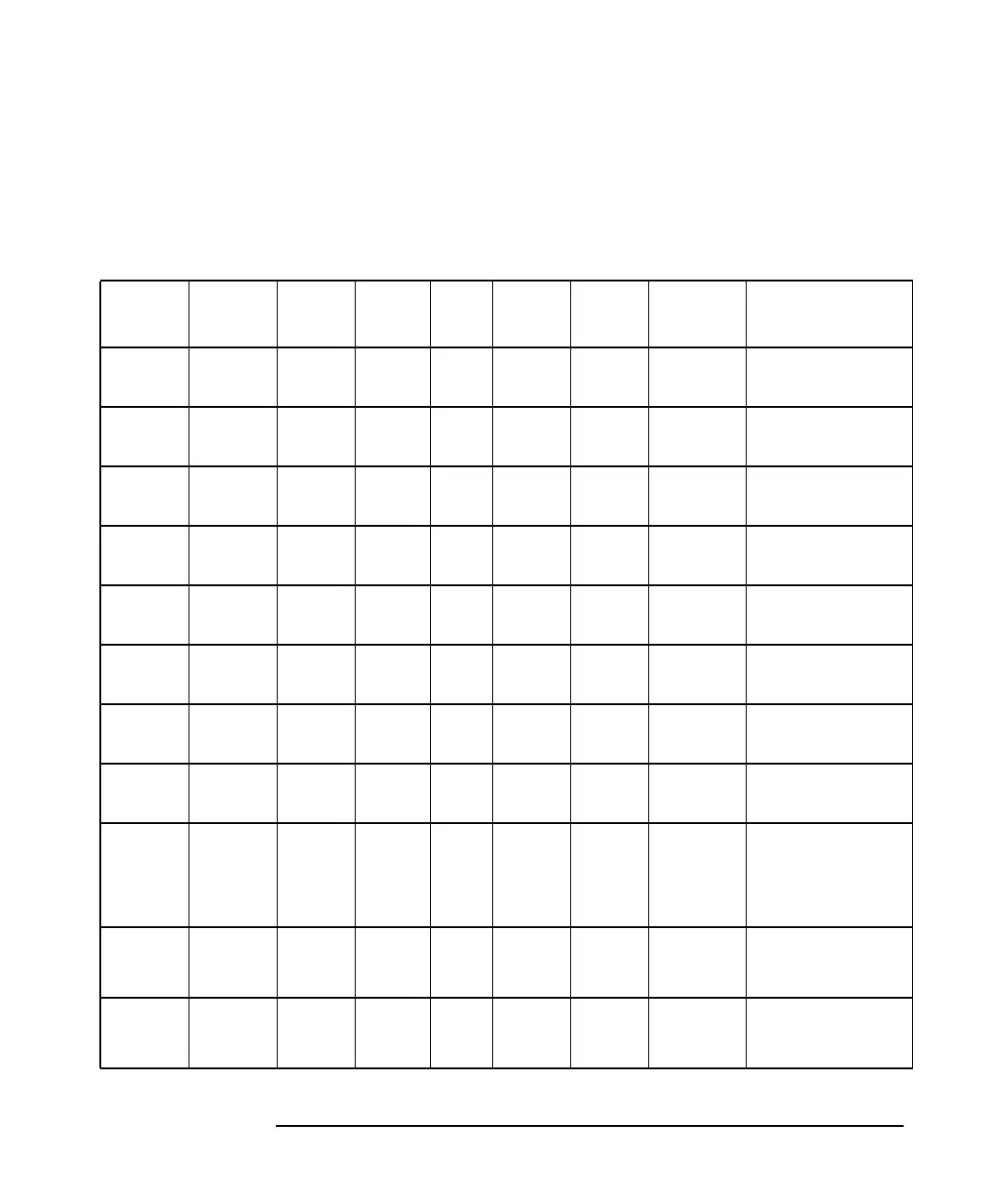
Table 5-3 Fan and Speed Control Scan
Sensor
#
Sensor
ID
Signal Lower
Limit
Mid Upper
Limit
Zircon
Pin
Winbond
Pin
Description
51h CPU0FA
NTACH
P1FAN
TACH
15 65 120 - Pin 20 Fan #1: Processor
1 fan tach
52h CPU1FA
NTACH
P2FAN
TACH
15 65 120 - Pin 19 Fan #2: Processor
2 fan tach
53h SYSFAN
TACH
FAN1T
ACH
10 29 60 - Pin 18 Fan #3: System
fan tach
54h PCIFAN
TACH
FAN4T
ACH
10 31 60 GPIO 0 - Fan #4: PCI fan
tach
55h HDDFA
NTACH
FAN5T
ACH
15 28 80 GPIO 1 - Fan #5: HDD fan
tach
56h PSUFAN
TACH
FANM 10 51 100 GPIO 3 - Fan #6: Power
supply fan tach
61h CPU0FA
NCTRL
WP1FA
NCTL
- - - - Pin 23 Fan #1: Processor
1 fan ctrl
62h CPU1FA
NCTRL
WP2FA
NCTL
- - - - Pin 11 Fan #2: Processor
2 fan ctrl
63h SYSFAN
PWM
WFAN1
23CTL
- - - - Pin 10 Fan #3: System
fan PWM (&
unused spare fan
PWM)
64h PCIFAN
PWM
FAN4C
TL
- - - GPIO21
PWM1
- Fan #4: PCI fan
PWM
65h HDDFA
NPWM
FAN5C
TL
- - - GPIO20
PWM0
- Fan #5: HDD fan
PWM
This manual downloaded from http://www.manualowl.com



 To Next Page