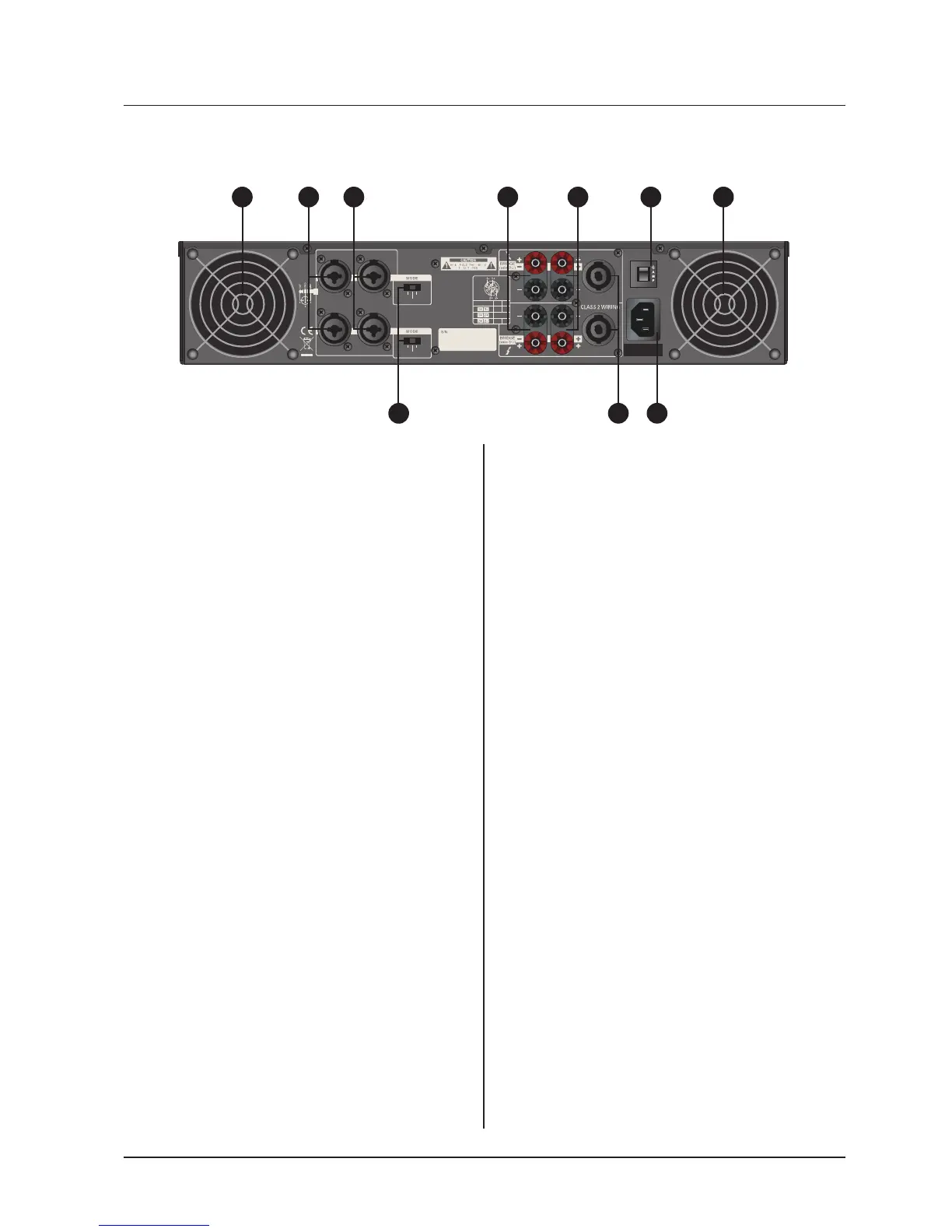
1. Fan
This is a variable speed cooling fan. Cool-
ing air enters the amplifier through the fan
ports located on front of the amplifier chassis,
Be sure not to block these ports when install-
ing the amplifier or other associated equip-
ment.
2. Input connectors
Connect the input source to these elec-
tronic balanced Combination connectors
using either XLR or 1/4” TRS plugs. The 1/4”
TRS and XLR plug configured as follows :
Pin 2 (Tip) hot, Pin 3 (Ring) cold, and Pin 1
(Sleeve) ground. We recommend the use of
balanced three-conductor cabling wherever
possible. Unbalanced two-conductor 1/4”
plugs can also be inserted into these inputs,
but you will get better signal quality and less
outside noise and hum if you use balanced
lines. Stereo signal should be connected to
all Channel 1~ 4 input jacks ; however ; when
operating the QA Series in Bridged Mono or
Parallel modes, use the Channel 1.3 input
jack only.
3.Bridge / Stereo / Parallel switch
This switch changes the amplifier op-
erating mode from either stereo or mono
bridged or parallel. You can place this switch
in “STEREO” position (center) for normal
stereo operation. When placed in “PARAL-
LEL” position, the channel 1 input signal is
routed to the power amplifier of channel 1&2
and the channel 3 input signal is routed to the
power amplifier of channel 3&4. When placed
“BRIDGED” position, the channel 1 input
signal only is routed to channel 1&2 again. In
this mode the channel 2 input is ignored.(The
channel 3 input signal only is routed to chan-
nel 3&4 in this mode the channel 4 input is
ignored.)
4. 5-way Binding Post
Connect each channel of the QA Series to
4 ohms or 8 ohms loudspeakers.Two pairs
of 5-way binding posts are provided for each
channel, so that paralleling of speakers is
possible.Connection to the binding posts can
be made with bare wire, banana plugs, or
spade lug terminations. Make connections to
all 4 channel terminals for Stereo or Parallel
Mode, or a single connection across the red
terminals of Channel 1 and Channel 2 and
channel 3 and channel 4 for Bridged Mono
Mode.
5. Speakon output connectors
You can use these to connect each chan-
nel of QA Series to 8 ohms or 4 ohms loud-
speakers. Using Speakon speaker cables,
make connections to all 4 channel connectots
for Stereo or Parallel Mode, or to the Bridged
mode connector for Bridged Mono Mode.
Rear Panel Controls
1 12 2 4 4
5 7
6
3
 Loading...