Shenzhen Hpmont Technology Co., Ltd Chapter 6 Function Introduction
HD30 Series Inverters User Manual ―117―
Motor overheating fault (F20.06
F20.07)
It can connect the electronic thermistor embedded motor stator coils to the inverter’s analogue
input in order to protect motor overheating. The connection is shown as the figure
F16.04.
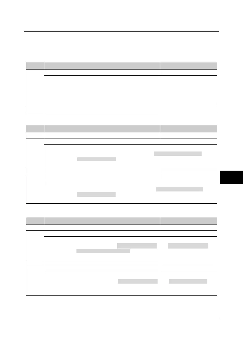
No. Name Description Range
factory setting
Motor overheating signal input type
0: Does not detect the motor overheating.
1: Positive charateristic (PTC).
2: Negative charateristic (NTC).
Note: Only when using HD30-EIO will F20.06 be enabled. It need correctly set the jumpers of
CN3 and CN4 to detect the motor overheating.
Thermistor value at motor overheating
Input and output phase loss fault (F20.08
F20.11)
No. Name Description Range
factory setting
F20.08 Input phase loss detection reference 0
50
30%
Input phase loss detection time
F20.08 value is a percentage of the inverter’s rated voltage.
When the inverter detects certain input voltage not hit the preset detection reference (F20.08) and
exceed the preset detection time (F20.09), the inverter will perform input phase loss alarm (E0015).
• When F20.08 or F20.09 is set to 0, the inverter will not detect input phase loss fault.
Output phase loss detection reference
F20.11 Output phase loss detection time 0.00
20.00
3.00s
F20.10 value is a percentage of the inverter’s rated current.
When the inverter detects certain output current not hit the preset detection reference (F20.10) and
exceed the preset detection time (F20.11), the inverter will perform output phase loss alarm (E0016).
• When F20.10 or F20.11 is set to 0, the inverter will not detect output phase loss fault.
PID reference and feedback loss fault (F20.12
F20.17)
No. Name Description Range
factory setting
F20.12 PID reference lose detected value 0
100
0%
PID reference loss detection time
F20.12 value is a percentage of the maximum reference source.
If the PID reference value is lower than the detected value (F20.12) in the detection time(F20.13), the
inverter will alarm E0025 fault (PID reference loss).
• When F20.12 or F20.13 is set to 0, the inverter will not detect PID reference loss fault.
PID feedback loss detected value
F20.15 PID feedback loss detection time 0.0
10.0
0.20s
F20.14 value is a percentage of the maximum feedback source.
If the PID feedback value is lower than the detected value (F20.14) in the detection time (F20.15), the
inverter will implement PID feedback loss alarm (E0026).
• When F20.14 or F20.15 is set to 0, the inverter will not detect PID feedback loss fault.
6
 Loading...

