5 Installation and commissioning
114
HSD S.p.A. © - h0104k01a.fm120718
5.8.3 Versions with MIL electrical connectors
The position of the electrical connectors is shown in paragraph 3.4.6 “Variations with MIL standard
electric connectors”
. The connectors are located in an electric box on which there's a tool manual
release button; to connect the button, refer to paragraph
5.8.4 “Tool release button”. The mobile
connectors (to be wired by the customer) are supplied with the electrospindle.
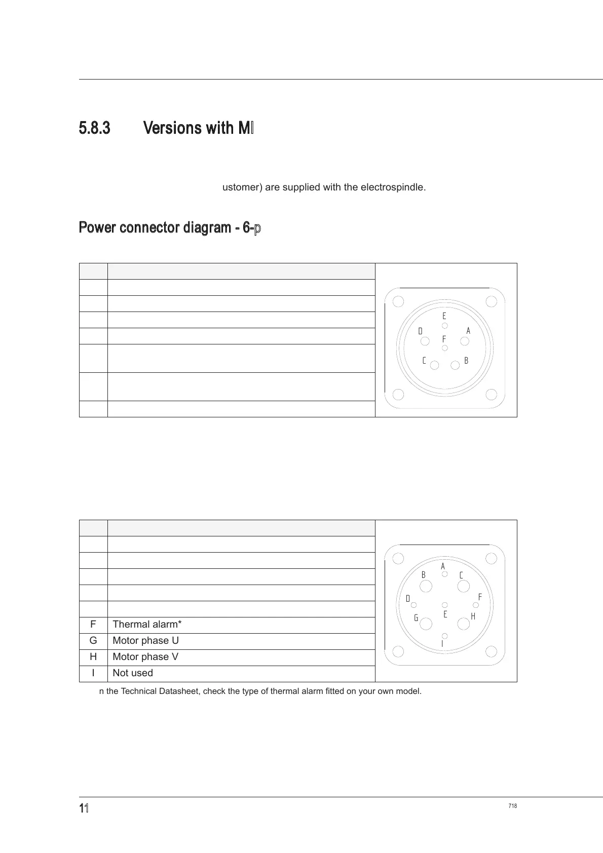
Power connector diagram - 6-pin version (fixed part)
Power connector diagram - 9-pin version (fixed part)
PIN DESCRIPTION user side view
A Motor phase U
B Motor phase V
C Motor phase W
D Earth
E
Depending on the version*:
thermal alarm** or not used.
*
The thermal alarm is connected to the power connector or the signal connector, depending on the version.
**
On the Technical Datasheet, check the type of thermal alarm fitted on your own model.
F
Depending on the version*:
thermal alarm** or not used.
- -
PIN DESCRIPTION user side view
A Not used
B Earth
C Motor phase W
D Not used
E Thermal alarm*
*
On the Technical Datasheet, check the type of thermal alarm fitted on your own model.
F Thermal alarm*
G Motor phase U
H Motor phase V
I Not used
A
B
D
C
E
F
A
B
C
D
E
F
G
H
I