HT7
EN - 5
4. OPERATING INSTRUCTIONS
4.1. INSTRUMENT DESCRIPTION
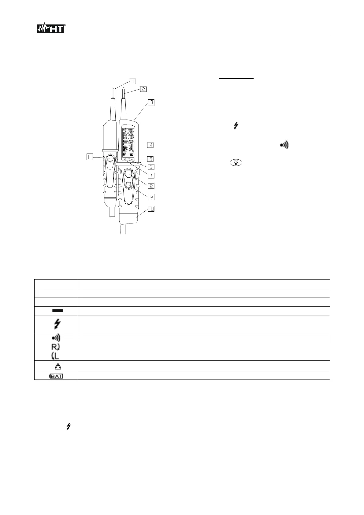
CAPTION:
1. L1 detachable probe
2. L2 fixed probe
3. White LED illuminator
4. LCD display
5. Voltage measurements
warning LED
6. Low impedance test LED
7. Continuity test LED
8. Low impedance switch (L2)
9. key to activate white LED
illuminator
10. Battery cover
11. Low impedance switch (L1)
Fig. 1: Instrument description
4.2. DESCRIPTION OF SYMBOLS AT DISPLAY
The following symbols can be displayed on HT7:
Symbol Description
DC voltage measurement
AC voltage measurement
Negative polarity on DC voltage measurement
This symbol is lighted up whenever the voltage between the probes
exceeds 50V, even if the batteries are low or have been removed
Continuity test
Clockwise phase sequence
Counterclockwise phase sequence
Detection voltage necessary to perform measurements
Low battery indication
4.3. INITIAL AUTOTEST
Before start any measurements perform the following checks:
Use the instrument on a known voltage source.
The " " symbol is lighted up whenever the voltage between the probes exceeds 50V,
even if the batteries are low or have been removed.
Short the L1 and L2 probes. The indicator lights, the buzzer sounds and the LEDs for
the continuity test light up. The LEDs for the low impedance test and the single-phase
voltage do not light up.