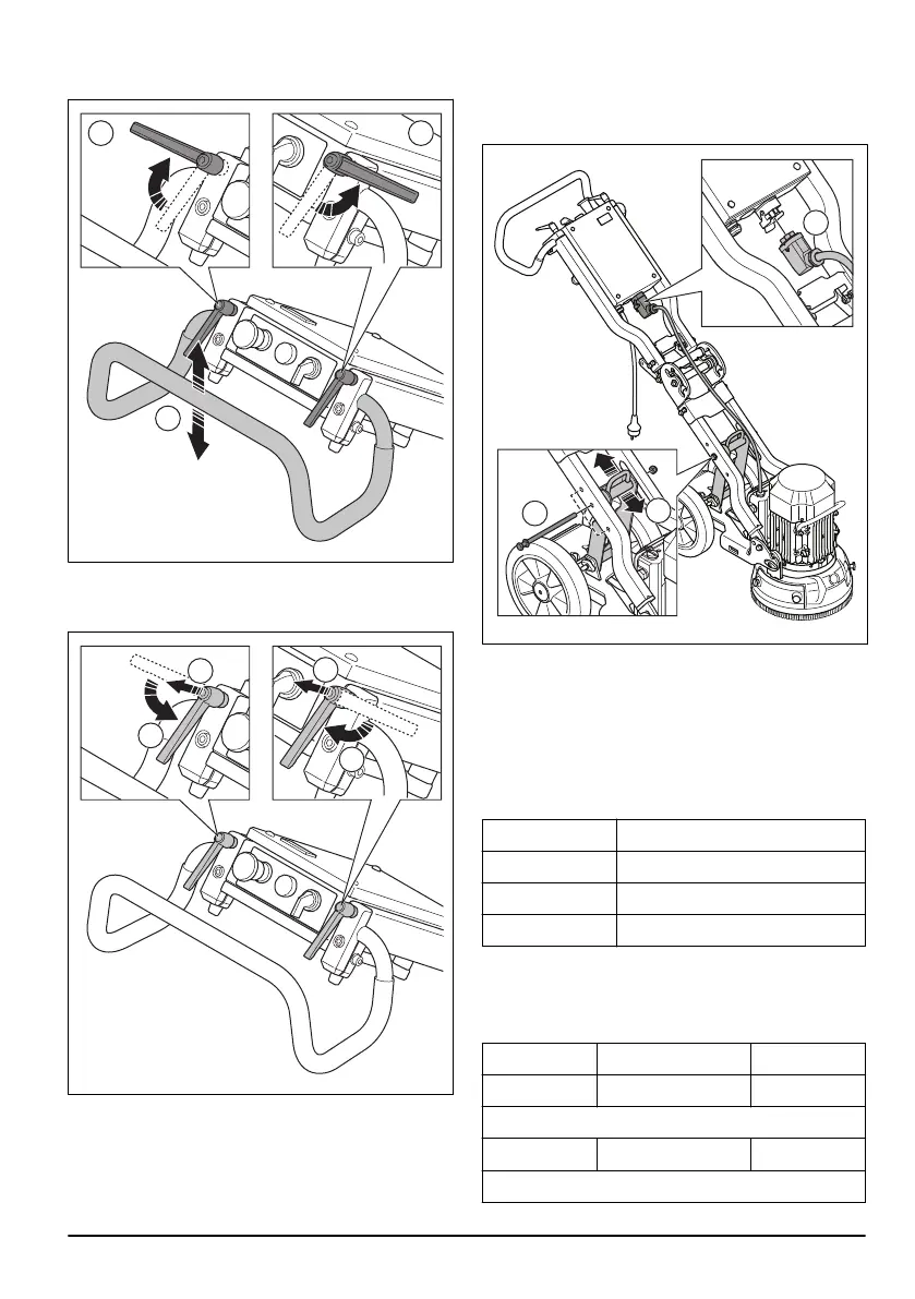
1. Loosen the lock knobs (A) and adjust the handle (B)
to idle position.
2. Tighten the lock knobs to set the position.
3. When the handle position is set, pull the handle lock
knobs up (A) and put them into idle position (B).
To adjust the frame height
The angle of the frame can be changed to divide the
weight of the chassis. This is to decrease or increase
the grinding pressure against the surface.
Adjust the angle to set up a good work position for
different operators.
1. Disconnect the motor cable (A) from the electrical
enclosure.
2. Remove the lock knob (B).
3. Select the applicable position (C) for the operation
and put the lock knob (B) in correct hole. The bottom
hole increases the grinding pressure and the height
of the handlebar. The top hole decreases the
grinding pressure and the handlebar.
Handle heights
Hole position
Handle height, mm/inch
Top 835/33
Center 925/36
Lower 1000/39
Grinding pressure
Refer to the tables for the grinding pressure against the
surface for each hole position.
Low, kg/lbs
Center, kg/lbs Top, kg/lbs
23/51 25/55* 27/60
With accessory counterweight
17/37 20/44* 23/51
*Factory setting
917 - 001 - 9