LP-314 Rev. 012 Rel. 003 Date 9.27.19
6
Households with small children, disabled, or elderly persons may
require a 120
o
F or lower temperature setting to prevent severe
personal injury or death due to scalding.
G. Water Temperature Adjustment
If the appliance is going to have a set temperature above 120
o
F, you
must use an ASSE 1017 rated mixing valve to avoid severe burns or
death from scalding temperatures.
F. High Elevation Installations
Natural gas at high elevation might contain less heating value than
typical 1,000 BTU/cu ft and therefore can cause improper air / gas
mix leading to improper combustion. For natural gas installations
above 3,000 ft, call your gas provider to determine the heating value
of the supplied natural gas.
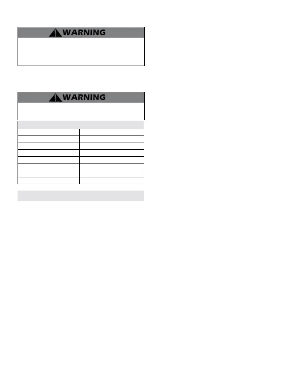
Approximate Time / Temperature Relationships in Scalds
120
o
F More than 5 minutes
125
o
F 1 1/2 to 2 minutes
130
o
F About 30 seconds
135
o
F About 10 seconds
140
o
F Less than 5 seconds
145
o
F Less than 3 seconds
150
o
F About 1 1/2 seconds
155
o
F About 1 second
Table 1 - Approximate Time / Temperature Relationships in Scalds
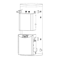
B. How the Appliance Operates
The Versa Hydro with Total System Control provides high eciency
central heating and domestic hot water from one appliance. Total
System Control manages system needs, ensuring maximum comfort
and ecient operation. Some features of the appliance are:
Stainless Steel Water Storage Tank
The storage tank is constructed of 316L stainless steel to provide
maximum corrosion resistance. Water blown foam insulation and a
plastic jacket provide superior insulation, allowing no more than ½
degree heat loss per hour.
High Eciency Heat Exchanger
The 90/10 copper nickel heat exchanger provides highly ecient
energy transfer. Hot gases from the primary circuit heat the combustion
walls. The walls transfer heat directly into the domestic water. The
secondary circuit then transfers the last bit of energy to the bottom
of the tank, where hot gases are converted to water vapor, giving the
appliance a combustion eciency of 98% and thermal eciency of up
to 96%.
Components included with the appliance:
• Intake PVC Tee with Screens
• Exhaust PVC Coupling with Screens
• Temperature and Pressure Relief Valve
• Installation Manual and Warranty
• User’s Information Manual
• Solar Addendum (S Models Only)
• Outdoor Sensor (Part # 7250P-319)
• Mixing Valve (7100P-315)
A. What’s in the Box
Part 2 - Before You Start
Remove all sides of the shipping crate of the appliance.
Modulating Combustion System
The modulating combustion system regulates ring rate based on
heat demand. Total System Control monitors tank operation, system
parameters, and controls the ring rate of the burner, providing only
the energy required to satisfy both domestic hot water and central
heating needs.
Total System Control
Total System Control automatically manages the central heating
and domestic hot water systems through the use of sensors.
These sensors monitor inputs (such as outdoor temperature, tank
temperature, and heating module outlet temperature) providing
data that allows accurate control of the entire system. You may
choose to use the control’s factory default settings or reprogram
system parameters to provide design exibility.
Hydronic Heating Module
The hydronic heating module connects to the storage tank through
two dip tubes. The rst dip tube draws heated water from the top
of the storage tank and circulates it through a brazed plate heat
exchanger to transfer the water’s stored energy to the hydronic
side of the plate. Once the energy is transferred, the water returns
through the second dip tube to a lower section of the storage tank
to continue circulating. A stainless steel circulator pump modulates
output, varying ow through the brazed plate heat exchanger
to meet domestic hot water and central heating demand. An
outlet sensor provides feedback to the control to assure accurate
temperature control.
Venting System
This appliance must be exhausted to the outdoors. Use only the
approved venting materials outlined in the Venting section of this
manual. Vent size can vary from 2” to 3” depending on the appliance
input rate. Special attention should be taken when selecting vent
location. Vents can run horizontally or vertically, depending on
system design, and should be supported as shown in the Venting
section of this manual.
Burner
The burner is constructed of high grade stainless steel and uses pre-
mixed air and gas to provide a wide range of ring rates.
Condensate Drain Connection
This is a condensing high eciency appliance with a condensate
removal system. Condensate is nothing more than water vapor
derived from combustion products, similar to that of an automobile
when it is initially started. It is very important that the condensate
line slopes away from the appliance and down to a suitable inside
drain.
If the appliance condensate outlet is lower than the drain, use a
condensate removal pump (Part # 554200, available from HTP). In
addition, local authorities may require a condensate neutralizer to
neutralize the condensate. Condensate neutralizers are made up
of lime crystals, marble, or phosphate chips. Neutralizers can be
installed in the eld by the installer and purchased from HTP (7450P-
212).
It is also very important not to expose the condensate line to freezing
temperatures or any type of blockage. Plastic tubing must be the only
material used for the condensate line. Steel, brass, copper, or other
materials will be subject to corrosion or deterioration. A second vent
may be necessary to prevent condensate line vacuum lock on a long
horizontal run. Also, an increase in pipe size may be necessary to
allow condensate to drain properly. Support of the condensate line
may be necessary to avoid blockage of the condensate ow.
Spark Ignition
The burner ame is ignited by applying high voltage to the system
spark electrode. This causes a spark from electrode to ground.
Outdoor Sensor
Monitors outdoor temperature and adjusts the set point to provide
greater eciency.
 Loading...