4
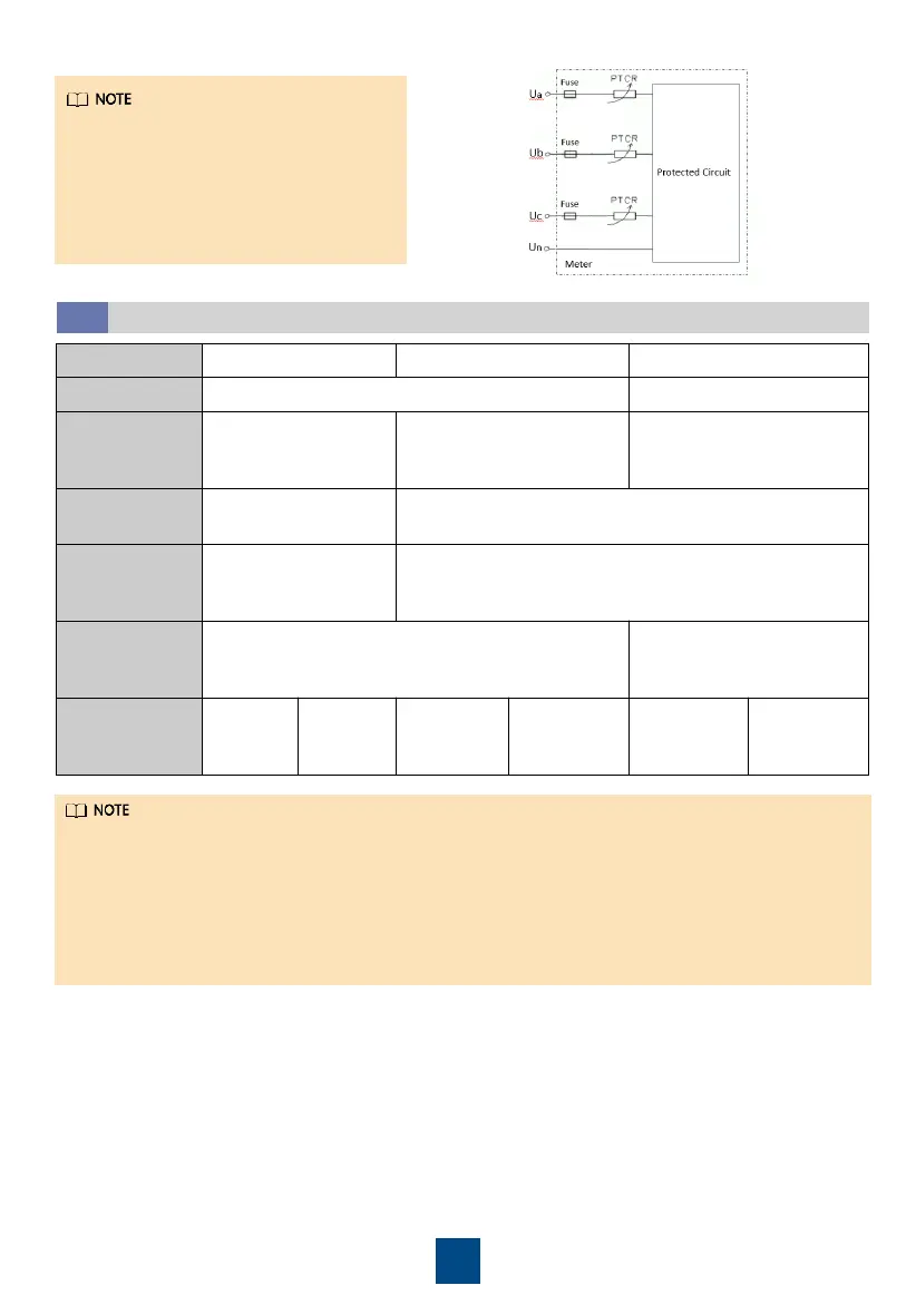
Each phase of UA, UB, and UC in the
Smart Power Sensor is connected with
a fuse and a thermistor to prevent
damage caused by external short
circuits. UA, UB, and UC do not need
external fuse protection.
Current ≤ 80 A > 80 A ≥ 0 A
Line voltage ≤ 500 V > 500 V
Connection
mode
Current and voltage
direct connection
Connection through
voltage direct connection
Connection through current
transformers
Connection
setting
Direct connection:
SPEC = 1 (default)
Connection through transformers:
SPEC = 0
Current
ratio
CT = 1
(default)
CT = Ratio of the installed
current transformer
Potential
ratio
PT = 1.0
(default)
PT = Ratio of
potential transformer
Wiring
mode
3P4W:
3P4W:
net = n.34
(default)
3P3W:
net = n.33
3P4W:
net = n.34
(default)
3P3W:
net = n.33
3.2
Wiring Scenarios
•
You need to set parameters after cable connections are complete. For details, see section 4
"Display and Parameter Settings".
•
This meter is generally used in commercial and industrial high-current scenarios. In external
CT scenarios, the precision of the secondary-side current is
±
5 mA. For example, if a CT with
a transformer ratio of 400/1 is selected, the error is
±
2 A. This meter is not recommended
in scenarios where the plant power is low or the control precision of the grid-connection
point is high. Instead, use a meter with higher precision.