ii
Contents
1 Precautions …………….…………………………………………............................………….1
2 Tools for Installation ……………………………………….............................………………….2
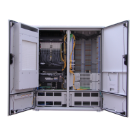
3 Appearance and Structure ……………………………………….............................…………….3
4 Installing the Cabinet on a Concrete Pedestal………….............................…………….8
4.1 Construct the Concrete Pedestal ………………………………………………………….8
4.2 Fastening the Cabinet ….………..................................................................12
5 Installing the Cabinet on an Underground Base……………...............................………..23
5.1 Appearance of the Underground Base............................ ...........................................23
5.2 Digging a Foundation Pit…... …... …... …... …... …...…...............................24
5.3 Laying the Underground Base.…..... .…......…........................................25
5.4 Filling Soil Back to the Foundation Pit………………………………………………26
5.5 Installing the Cabinet on the Underground Base..................................28
6 Routing Cables ………………………………………………...............................………..32
6.1 Routing the Cabinet PGND Cable.......................................................................32
6.2 Connecting Power Cables(AC Power Supply) ………………...............................34
6.3 Connecting Power Cables(RPS Power Supply). ………........................................36
6.4 Diagram of Cable Connections Between the RPS and MDF (RPS Power
Supply)………………………………………………………………………………….……. 39
6.5 Installing the AC+ RPR Power Module........................................................40
6.6 Connecting Power Cables(AC+RPR Power Supply).…........................................41
6.7 Diagram of Cable Connections Between the RPS and MDF (AC+ RPR Power
Supply)…………………………………………………………………………….…….45
6.8 Connecting External Subscriber Cables(Copper Configuration or Optical/Copper Mixed
Configuration)………………………………………………………………………….…….48
6.9 Connecting Optical Cable and Optical Fibers (Upstream)..... .... ................................50
6.10 Connecting Optical Cable and Optical Fibers (Downstream, Optical
Co nfigu rat ion)……………………………… … .………… ……… ...............51
6.11 Connecting Optical Cable and Optical Fibers (Downstream, Optical/Copper Mixed
Configuration) ……...................................................................53
6.12 Installing the Door Status Sensor Cable and Temperature Sensor (Scenario Where
the Battery Cabinet Is Deployed).... ............ ............ ......................56
7 Installing the Electronic Door Lock System…………. …………. …………. …………..58
7.1 Appearance and Structure …….……….........................................................58
7.2 Installing the CCU …….………................................................................59
7.3 Installing the Door Lock(BOM: 02311EYT).………...................................60
7.4 Connecting the Power Cable of the CCU..…...................................63
7.5 Installing the Anti-Theft Screw ………..…........................................ 64
7.6 Post-Installation Check ……................................................................ 66