L
1
13 14
XT2
UPS OutputUPS Input
QFX4 QFX3 QFX2 QFX1
52
N L
N L
XT1
Main Input
L
15 16
11 12
76
N
8
A/C
N
L
XT3
XT4
N L N L N L N
XT5
Battery Input Battery Output
BAT_In+
BAT_In-
BAT_Out+
BAT_Out-
3
4
N
L
FU
N
ECC
1
2
3
4
QFX5
9 10
N L
17
18
COM1/AIDI_1
COM2/AIDI_2
COM3/AIDI_3
COM5/AIDI_5
COM7/AIDI_7
COM4/AIDI_4 COM6/AIDI_6 COM8/AIDI_8 POE
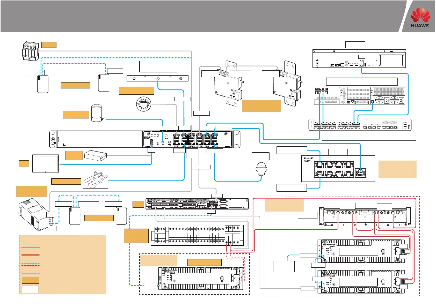
FusionModule500 Smart Mini Data Center Management System Wiring Diagram
(02116411, 02116412)
RS485_IN
RS485_OUT
RS485_IN
PAD
WiFi
module
RS485_IN
RS485_OUT
RS485_IN
UPS
UIM20A
RS485_OUT
RS485_IN
Cabinet electronic
clasp lock
RS485_IN
Note:
For a 02116411 cabinet,
the smart rPDU can be
configured.
Smart cooling
product
IVS1800
USB
4G
AI/DI_1 AI/DI_2
COM1
/AIDI_4
LAN1/POE
WAN_1
COM3/12V
COM4/CAN
COM2/
AIDI_5
MON3
COM
GE1
W&T
ECC
Smart rPDU 1
Smart rPDU 2
AI/DI_3
COM_IN
BAT+
BAT-
......
RTN+
-48V
COM_OUT
COM_IN
COM_IN
COM_OUT
BAT+
BAT-
BAT+
BAT-
LAN2/POE
01
Rack-mounted fire
extinguisher
LAN1/POE
Signal cable or ELV cable
Power cable
Pre-connected cable
Reserved cable
(connect to device onsite)
Optional components
Standard component
Description
ECC800 (front)
SPD
4G antenna
Smoke detector
T/H sensor
Water sensor
T/H sensor
Power
distribution
subrack
Lithium battery
Note:
One battery is configured
onsite.
Build-out
resistor
Lithium battery 1
Lithium battery N
Note:
Two or more batteries are
configured onsite.
Busbar
Camera
LAN switch (24-port switch as an example)
Server (2288X V5 as an example)
 Loading...