Scenario 2: The UPS Obtains Power from the ESS
1. Remove the short-circuiting bar from 1–2 and insert it to 2–3 on the XU terminal block.
2. Remove the short-circuiting bar from 6–7 and insert it to 7–8 on the XU terminal block.
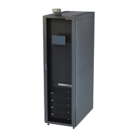
3. Connect the two armored cables to the ground points on the rear panel of the control unit
cabin.
4. UPS output: Connect the PE cable (provided by the customer) to the ground bar of the
control unit cabin, and connect the L and N wires (provided by the customer) to switch
5FCB2.
5. Install a UPS switch 5FCB (provided by the customer).
6. Connect the live wire 1775 and neutral wire 1777 (obtained from position 2 in the figure).
7. UPS input: Connect the PE cable (provided by the customer) to the ground bar of the
control unit cabin, and connect the L and N wires (provided by the customer) to switch
5FCB.
 Loading...


