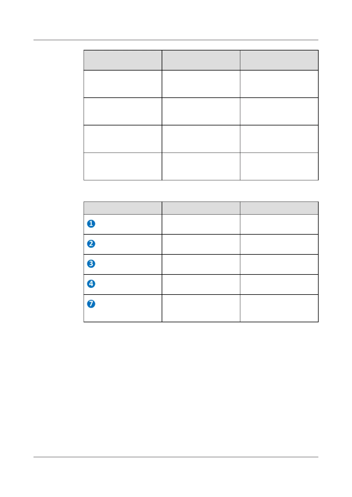
Bracket to Be Adjusted Parameter to Be
Adjusted
Default value (dB)
ATT0 Level of combined CATV
and downstream DOCSIS
signal of the RF OUT0.
4
ATT1 Level of combined CATV
and downstream DOCSIS
signal of the RF OUT1.
4
ATT2 Level of combined CATV
and downstream DOCSIS
signal of the RF OUT2.
4
ATT3 Level of combined CATV
and downstream DOCSIS
signal of the RF OUT3.
4
No.
Test point Function
TP.1 Tests level of the RF OUT0
port signal.
TP.8 Tests level of the RF OUT1
port signal.
TP.9 Tests level of the RF OUT2
port signal.
TP.4 Tests level of the RF OUT3
port signal.
TP.7 Tests level of combined
CATV and downstream
DOCSIS signals. (Main)
5.3 Adjusting the Upstream DOCSIS Signal Level
Step 1 Confirm the CM-side output level of the RF OUT port and record it as A. Run the display
cable modem extended-tx-power command to query Extended US TX Power. A =
Upstream TX Power - cable line attenuation.
Step 2 Run the cable upstream command to configure the upstream receive level of DOCSIS
module (B). The default value is 6 dBmV.
Step 3 Input single-tone signals (20 MHz and 40 MHz) into the test points of the RF OUT port,
respectively. Set the signal level to A+20 dBuV.
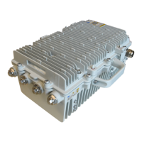
MA5833-DD60
Hardware Commissioning Guide
5 Adjusting the Signal Level
Issue 01 (2018-12-26) Copyright © Huawei Technologies Co., Ltd. 12