12
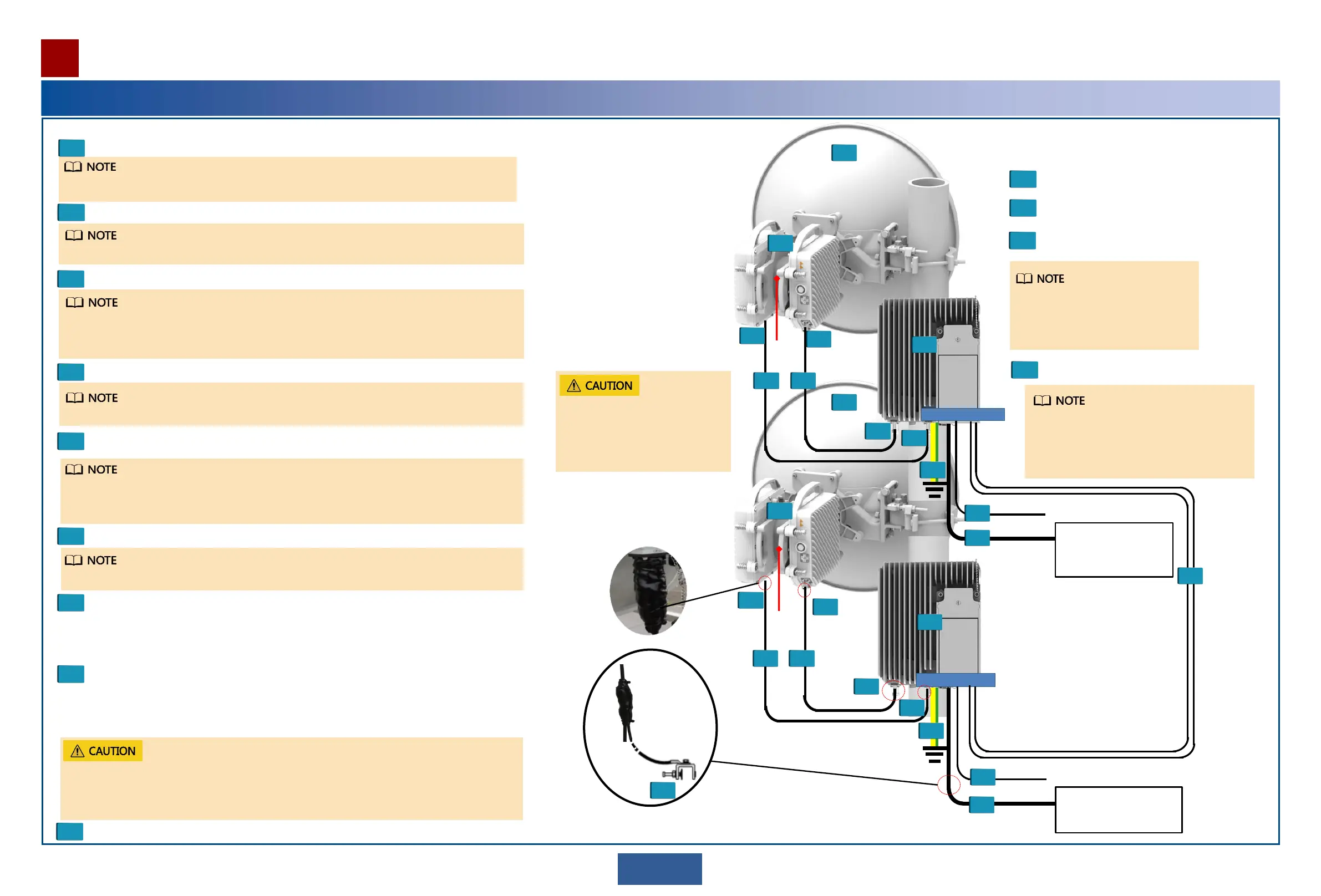
• For the method of making and laying out an IF cable, see the RTN XMC ODU Quick
Installation Guide.
• The length difference between the four IF cables must not exceed 30 cm.
3
Install an OAU 2A on a wall or pole.
• Determine whether to install an OAU 2A on a wall or pole based on actual conditions.
• If an OAU 2A needs to be installed on a tower, it is recommended that you install it at
the foot of the tower to facilitate maintenance.
4
Install a ground cable.
5
Install an outdoor fiber or network cable.
• Connect an outdoor fiber or network cable to a port in the maintenance compartment.
• Lay out the outdoor fiber or network cable.
• Attach a yellow label to the fiber or network cable, and write a number on the label
according to the plan.
7
Install a DC power cable.
• Connect a DC power cable to the DC power port in the maintenance compartment.
• Lay out the DC power cable.
• Select ground points for the DC power cable, and install ground clips.
• Attach a matte white label to the DC power cable.
8
Install IF cables.
Connect the IF ports of the OAU 2A and each XMC ODU using an IF cable.
9
Installation procedure
Waterproof ground clips and IF cable connectors.
Install the device-side ground cable before you climb up the tower.
Follow the antenna installation guide to install the antenna.
1
Install the ODUs on to the OMT. Connect the OMT and the antenna.
2
For the method of installing an XMC ODU, see the RTN XMC ODU Quick Installation Guide.
6
Install MIMO cascading cables.
Ensure that port MIMO1 connects to port MIMO1, and port MIMO2 connects to port MIMO2.
Before installing a cable, bind the cable section that links the cable connector to the pole. This will
protect the cable connector from damage. Ensure that the length of cable running from the
binding point to the OAU 2A is sufficient to attach the cable connector to a service port on
the OAU 2A.
The GE1(e) or GE2(e) port can be used to
transmit/receive electrical services, and the
GE3(o) or COMBO port can be used to
transmit/receive optical services. In this
example, the GE3(o) port is used.
The vertical distance between two antennas must meet the requirements specified in the
network plan.
Ensure that the poles where two
antennas are installed at a
MIMO site are in parallel.
Otherwise, the XPI may fail to
be adjusted to a proper range.
OMT
OMT
To NodeB
PWR GE(0) MIMO
To NodeB
MIMO cascading
cables.
1
1
2
2
3
3
4
4
55
55
7
7
6
8
8
Connected to a power
supply device
Connected to a power
supply device
PWR GE3(0)
MIMO
Grounded using
a ground clip
DC power
cable
DC
power
cable
8
9
9
9
9
9
9
9
9
Use the Web LCT to configure NE data.
Align antennas.
Power on the OAU 2A.
Commissioning procedure
1
2
3
4
Installing the OAU 2A
4Installation at a 4x4 MIMO Site
Check the installation.
4
You can use an alignment scope to
align antennas. For details about how
to install an alignment scope, see the
appendix.
 Loading...