18
10
2
1
4 5 8
9
11
3
6 7
3. Power-On Procedure
For details, see the UPS2000-G-(6 kVA–10 kVA) V100R001 Quick Installation Guide and UPS2000-G-(15 kVA–20 kVA)
V100R001 Quick Installation Guide.
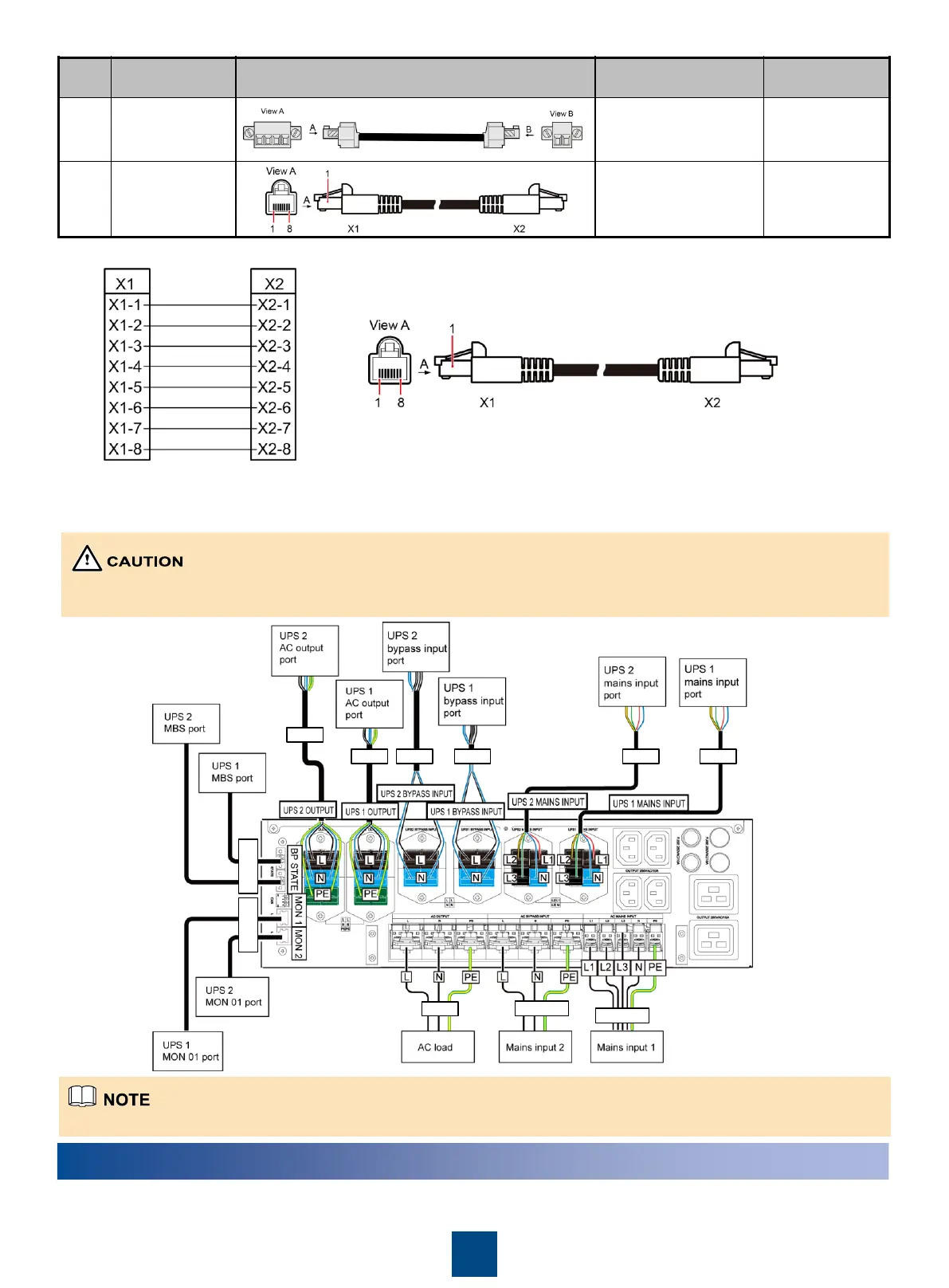
Connecting cables to the PDU for a 1+1 UPS2000-G-15 kVA/20 kVA parallel system (Three-phase input single-phase
output and Two Mains Input)
MBS is short for maintenance bypass switch.
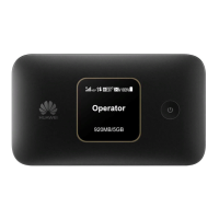
Mapping between cable connectors for CAN communications ports
Connect cables from bottom to top: Install cables for devices at the bottom and then devices on the top. When connecting
cables to one device, connect those at the bottom first and then those on the top.
Install the battery pack front panel after cables are properly connected.
 Loading...