Secure mounting brackets to the chassis with M4 screws.
Step 1
Install four floating nuts on the front mounting rails, two on each side. Leave a distance of 1 U between
the two floating nuts on each mounting rail.
Hold bottom of the chassis and move the chassis into the cabinet/rack.
Use M6 screws to secure the chassis onto the cabinet/rack.
Connect the ground cable. Connect the M4 lug (with a smaller hole) to the ground point at the rear of
chassis and the M6 lug (with a larger hole) to the ground point on the cabinet/rack.
Step 2
Step 3
Step 4
Step 5
Installation Procedure
4
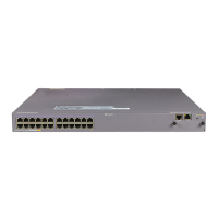
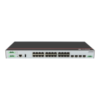
S5720I-28X-SI-AC&S5720I-28X-PWH-SI-AC S5720I-12X-SI-AC&S5720I-12X-PWH-SI-DC
M4 screw
Scenario 3: Cabinet/Rack Mounting
S5720I-SI can be installed in a 19-inch standard cabinet/rack or an outdoor cabinet. Cabinets purchased from
other vendors must have enough space for equipment installation.
The cabinet/rack must have reliable ground points to ground the switch.
Width of the mounting rails of an outdoor cabinet:
The mounting rails supported by the standard mounting brackets delivered with the S5720I-12X-SI-AC and
S5720I-12X-PWH-SI-DC must have a width of 272.5 mm to 278.5 mm.
The mounting rails supported by the standard mounting brackets delivered with the S5720I-28X-SI-AC and
S5720I-28X-PWH-SI-AC must have a width of 462 mm to 468 mm and support switch installation in a 19-inch standard cabinet.
Installation of the S5720I-12X-SI-AC and S5720I-12X-PWH-SI-DC in a 19-inch cabinet requires front mounting brackets (part
number: 21240477), which can be purchased separately.
Ensure that the outdoor cabinet has sufficient installation space and its depth is not less than that of the switch.
In addition, pay attention to the following:
If G.657.A2 short-jacket optical fibers are used, the distance between the front panel of the switch and the front door of the
cabinet must be at least 55 mm.
If G.652 long-jacket optical fibers are used, the distance between the front panel of the switch and the front door of the cabinet
must be at least 85 mm.
Leave at least 50 mm clearance at the rear and both sides of the chassis for heat dissipation.
Install a mounting bracket on the other side in the same way.
The captive screws and M6 screws are not delivered with the switch and need to be separately purchased if
needed.
The length of three adjacent mounting holes may not be 1 U. Observe the scale ticks on the mounting rails
when installing floating nuts.
Before You Start
 Loading...